Alex's 379 Cleveland, Part 1
This page: www.bacomatic.org/~dw/alex379/alex379a.htm
Main page: http://www.bacomatic.org/~dw/index.htm
Last Updated: 16 Jul 2003
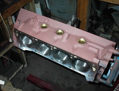
Block:
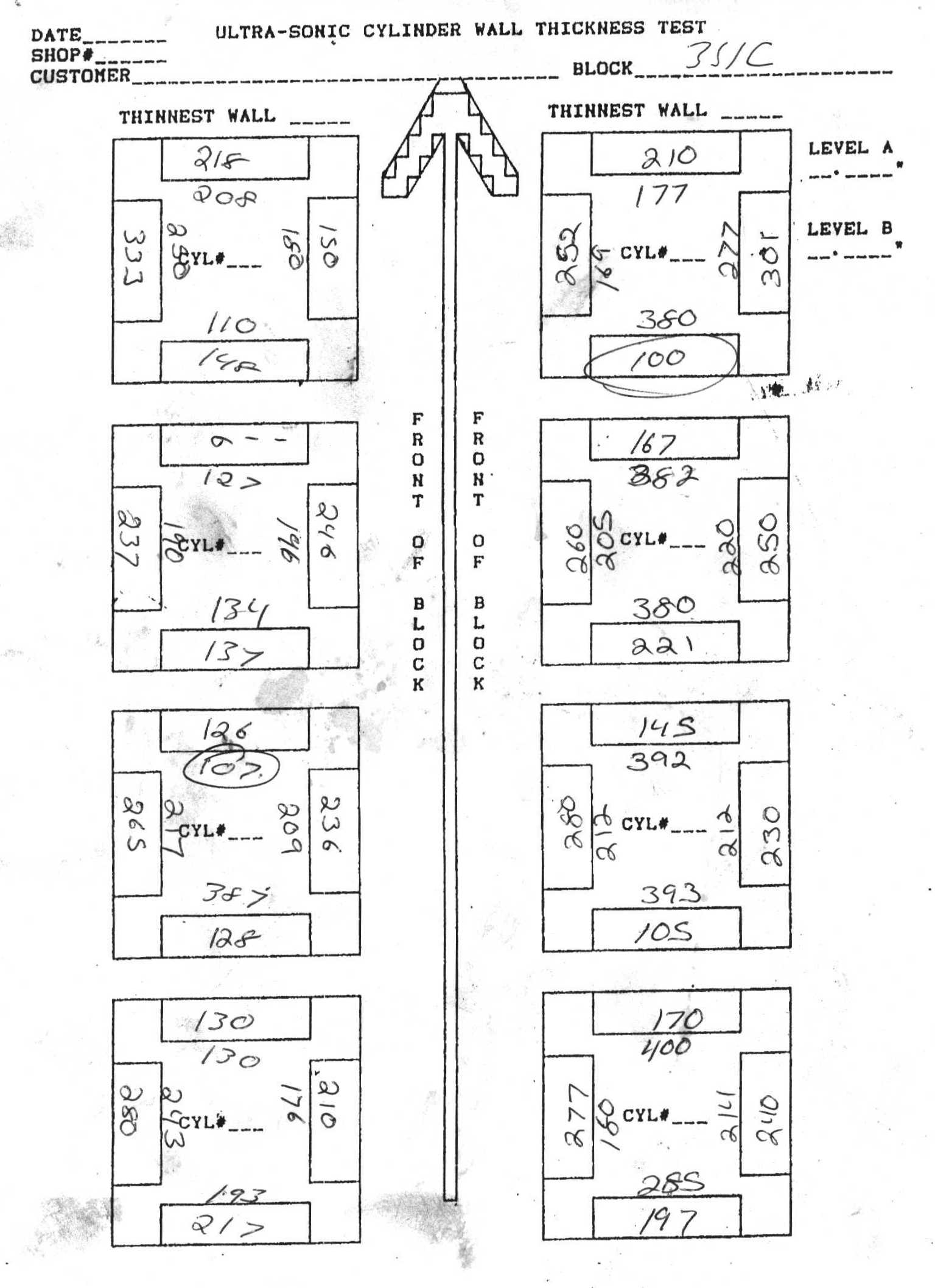
Sonic test results for the Pantera's 4-bolt Cleveland block. It's a bit thin
in several spots, and it had to go .040-over to clean up some wear at the tops
of the bores. I wound up offsetting the boring bar on each hole, taking the
minimum off the thin sides.
This Cleveland is not much thinner than several other blocks I've had checked,
though.
I farmed the sonic check out to another shop; they're the only ones around
here with one of those little $1,000 toys. One is high on my list... they do
a good job with it, eight points per hole. I have seen sonic charts from
places that only check two!
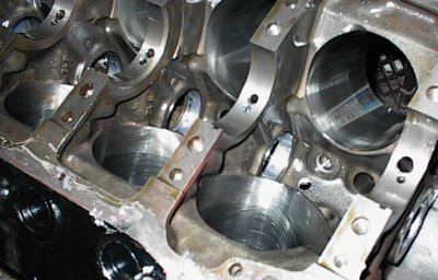
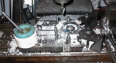
I tapped the cam bearing holes for oil restrictors, and restricted the
driver's side lifter gallery to .125". Solid lifter drag engines use .060" or
.070", but hydraulics need more oil to work right.
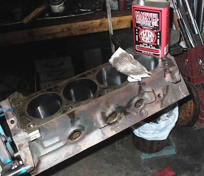
Out of the honing tank. It's made a second trip through the caustic tank,
then hit with soap and water and a brush. And a little oil on a paper towel
is still able to get that much stuff from the cylinder walls. The honed
surface is an ideal place for tiny pieces of broken-off grit from the stones
and microscopic metal particles that are removed from the cylinder wall. This
is just a preliminary cleaning to get the major gunge out; it'll get cleaned
again before final assembly.
All threaded holes get chased. The cam bearings and driver's side lifter
gallery are drilled and tapped for oil restrictors. It's a hydraulic lifter
engine, so the restrictors have to be sized appropriately. It will also get
custom pushrods with .040" restrictors.
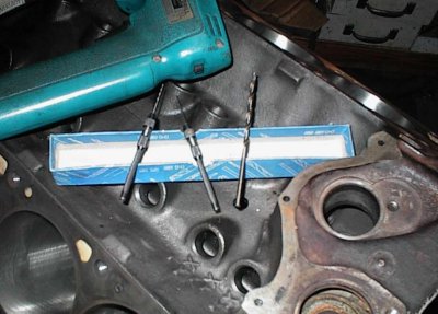
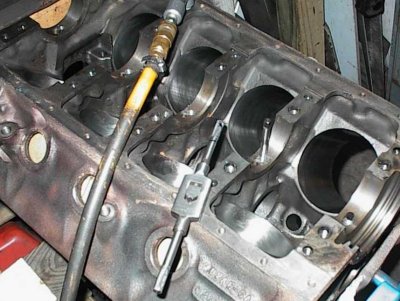
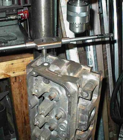
Drilling the block for the distributor gear oil hole. I do this to most Ford
engines nowadays. The tiny hole shoots oil directly into the gear teeth
instead of depending on splash from the crankcase. Long 1/8" drill goes most
of the way through the 3/8" or so of cast iron, .060" and .030" drills break
through to the distributor shaft oiling passage. You use a big drill for most
of the hole since the little ones are easy to break.
Ford machines the cam bores from both ends, installs the cam bearings, then
machines the bearings themselves to get correct alignment. Most of the time
you can drive in new bearings and everything works fine. In this case, there
was a slight bind on the cam. This scraper is made out of an old Cleveland
cam, modified with an angle grinder.
The binding area was just a little spot on the #1 bearing. Oddly enough, all
the ones I've had to scrape, the tight area was on #1...
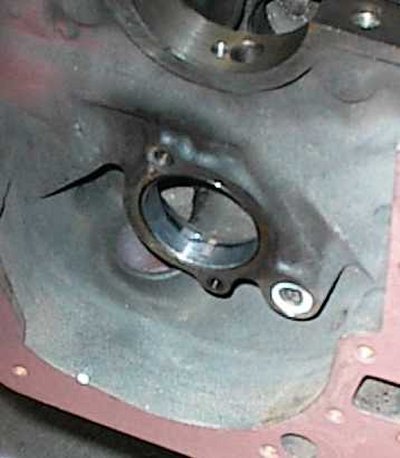
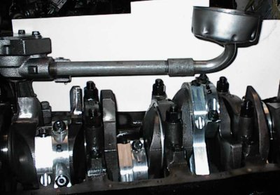
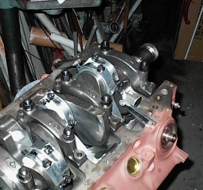
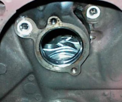
Oil hole. The engine is mostly assembled in this picture, with the drive rod
and intake in place.
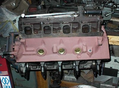
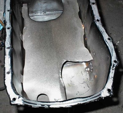
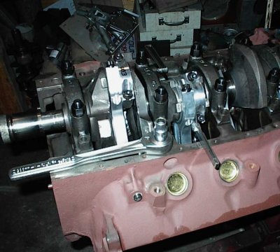
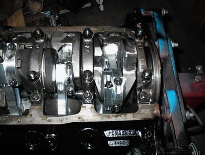
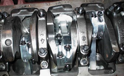
The mains are torqued, the cylinder bank is half-full of Hard-Blok concrete
filler, the heads are torqued to stress the block. One of the Cleveland's
weaknesses is that, though the cylinders are no thinner than most other Fords,
they're very long, which makes them less able to resist side thrust from the
pistons. This is a nitrous motor, so it's even more important to get good
cylinder support. I knew from previous experience that a half-fill wouldn't
make it run hot or cause other problems, and it will more than double the
cylinder walls' ability to handle side loads.
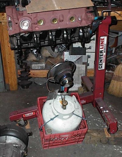
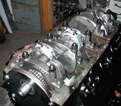
Normally it takes a day for the filler to cure. The next day I went out,
tilted the block the other way, started to mix the batch for the other side...
and noticed filler oozing out onto the floor! The temperature in the shop was
in the mid 30s over the weekend with the heat off. Concrete won't set when
it's that cold. A "learning experience."
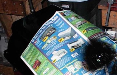
I put a small propane heater under the block, then draped some sheet metal
panels around to keep as much of the heat in as possible. The heater kept the
block warm to the touch. The filler set as usual.
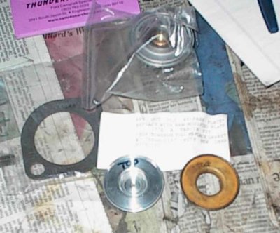
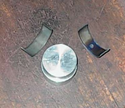
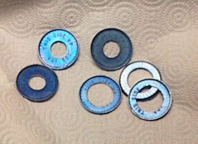
Clevelands take an oddball thermostat with a "foot" on the bottom to open
or close the restrictor orifice. Some parts books give the wrong part number,
and the store will give you a Windsor thermostat, which fits just fine, but
doesn't have the "foot", so the bypass will never close and the engine can
overheat.
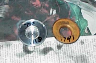
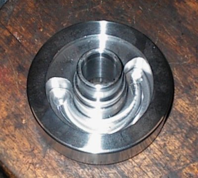
The disc on the right is the stock Cleveland bypass restrictor. The one on the
left is an aftermarket restrictor from one of the Pantera vendors. It forces
more water through the radiator and lets less recirculate inside the block.
Not all Panteras have cooling problems, but it's common enough that we're
taking some precautions while everything is apart. Alex also upgraded to a
massive aluminum radiator and all-new stainless steel plumbing while the
engine was out.
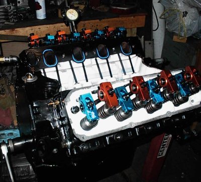
Here we are, finally - all ready to begin assembly. There have already been
several trial fits to check the deck height, crank clearance, cam/rod
clearance, piston/valve clearance, et cetera.
Pistons:
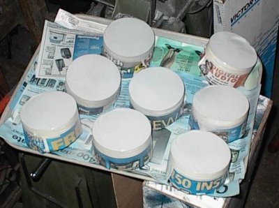
$750 worth of custom-made JE pistons get sandblasted before coating. Tops are
coated with Tech Line CBC2 thermal barrier.
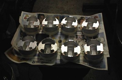
Sides are coated with TLML moly resin. The pistons run on an oil film, and
the moly resin doesn't really do anything useful as far as reducing friction.
However, the thickness of the coating adds to the diameter of the piston,
giving you a tighter fit without worry about having a piston gall in the bore.
Any excess coating wears off; the rest floats on the oil film. The larger
bearing area helps stabilize the piston in the bore, and helps transfer heat
from the piston to the walls. It's great stuff, but it doesn't work quite the
way the advertising would make you think.
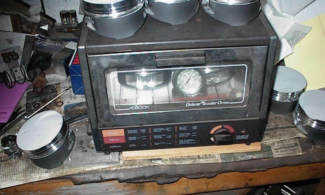
And of course, we bake. The Galloping Gourmet always seemed to find some way
to set something on fire; fortunately my baking is less dramatic.
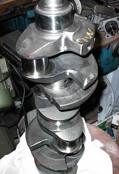
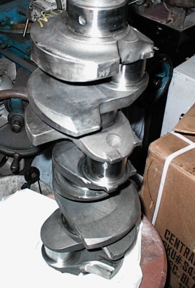
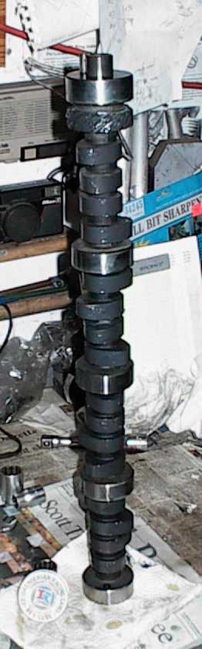
Crank:
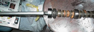
Stroking the rod journals on the crank grinder. That's 2.311" Cleveland size
on the right, 2.100" (well, a little oversize at this point) Chevy on the
left. It takes half a day at the grinder to do all four journals. The sides
of the wheel are dressed with a special tool to give a large side radius.
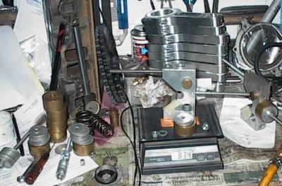
All the bits have been weighed and equalized, now it's time to build the
bobweights for balancing.
Australian-made ROMAC harmonic balancer. They whittle them out of a big chunk
of steel on CNC equipment. I kept the stock 28oz external balance; it
stresses the crank less than an internal balance.
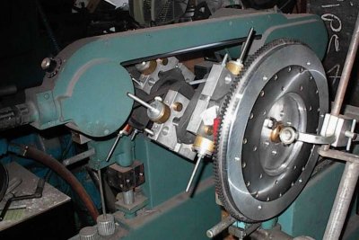
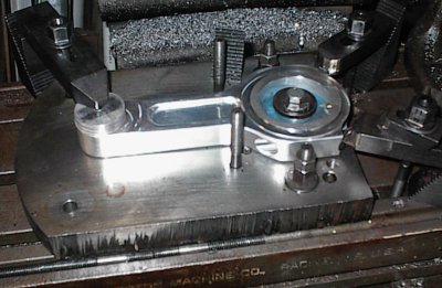
Balancing. The lightweight rods and pistons meant a lot of weight had to come
off the countweights. Centerforce aluminum flywheel has a bolted-on
counterweight to match the stock balance.
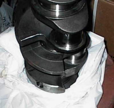
The normal method is to drill holes in the counterweights. I reduced the OD
of the front counterweight substantially, then beveled the edges. The OD
reduction reduces the rotating inertia of the crank more than drilling, which
lets it spin up faster in the engine.
I was just removing some unwanted weight, not getting crazy about knife-
edging, so I only worked where it was easy to get to with the angle grinder.
You can see some of the counterweight reduction here - about 1/2" at the
middle, 3/4" or so at the edges. It's round instead of slightly football
shaped like before.
Some of the beveling at the back. Not as much weight had to come off the back
as the front. This is normal; the harmonic balancer hangs out farther from
the #1 main than the flywheel is from #5, and even though they total 28 oz-in
of imbalance, it's not distributed evenly across each end.
Rods:
Setting up to narrow the rods. This was done before balancing, of course.
Here we go. Aluminum is much easier to cut than the usual forged steel! I
had to clamp on the bolt heads and pin end to hold the rods in place; the
aluminum rods are so thick they get machined across the areas I normally use
for clamping.
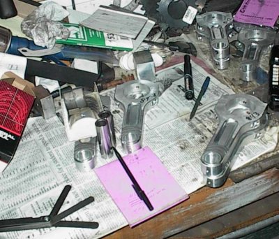
The machined rods get dressed to precise width on the belt sander. The beams
aren't exactly centered in the forgings, and they're about as wide as
you can fit on a Ford journal. You can see the sander marks on the rod in the
foreground, where the offset beam got trimmed a bit. Doesn't hurt a thing,
and it's necessary for proper counterweight clearance, but if you didn't know
what was going on you'd probably scratch your head and say "Duh?"
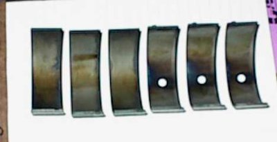
Fancy TRW racing-type rod bearings with dowel hole, already chamfered on one
side. The racing bearings don't have the usual indium overlay, so they look
strange. They're as hard as the clappers of Hell, too.
Spud for narrowing the bearings. I didn't have to take too much off. The
stock Ford bearings are a bit narrower than the journals. I widened the
journals a bit while stroking the crank, and the new bearings are as wide as
they can be without rubbing something. They still have less bearing area than
the originals, but it's a non-issue.
Oiling:
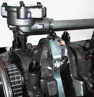
There's sufficient clearance here, though the picture doesn't look like it.
Ooohh, a little close there. The pickup tube had to be adjusted a bit so the
rod wouldn't hit. The pickup and pan are from a later Amerisport Pantera.
The ordinary NPT pipe fittings look tacky, but they worked just fine for
Amerisport.
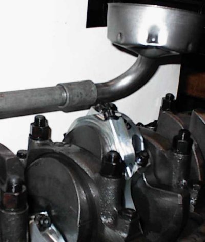
Another "before" shot. There was enough slack in the oil pump mounting holes
so the tube cleared if you held the pickup away from the rod while tightening
the pump bolts, but I was afraid the tube would vibrate or flex while the
engine was running.
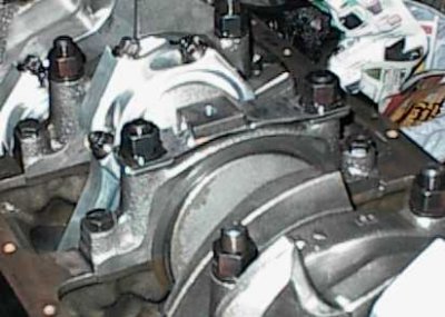
There was enough thread left on the main studs to run a strap from stud to
stud. I welded a drilled and tapped block to the strap to get something to
bolt a pickup tube brace to.
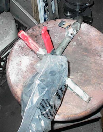
I welded some angle and flat stock to the pickup.
Plastic bag and spring clamps to keep weld spatter off. It has to be
disassembled and cleaned anyway, but MIG spatter is insidious about getting
into places where it shouldn't.
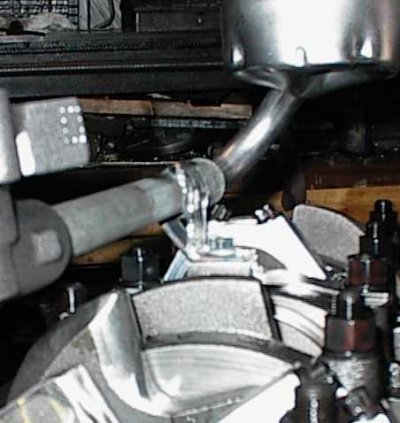
Fuzzy image of the pickup support bolted into place. It's not fully
triangulated, but the car had made it 28 years without it moving enough to
crack the threaded fittings; I figured it wouldn't be an issue.
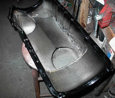
10-quart Kirk Evans pan, modified from a stock Cleveland pan. Very nice
baffle setup means no separate windage tray is needed. The sump isn't full-
length since stock Panteras have a crossmember that runs under that spot.
The Pantera's oil temp sender goes into the front of the pan. The new sender
was different from the old one, so an adapter bushing had to be welded in. Of
course, we found this out *after* the pan had been powder coated. I masked it
off and touched it up with some gloss black spray paint. It worked okay.
Stock, Speed-Pro, Melling, and other brands of oil pumps vary slightly in
external shape. The baffle in the pan was tight against the stock pump and
had to be trimmed slightly to clear the new Melling pump. Of course this only
showed up on final assembly, after the joint surfaces were covered with
sealer. You can't get a set of tin snips in at the right angle to do a neat
job. After mangling the metal, I had to grind the sharp edges smooth, then
clean the pan again, remove the dried sealer from the pan and block, and so
forth.
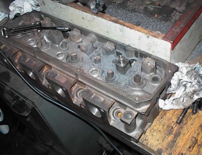
Heads:
The engine in a Pantera sits level instead of at the usual four to five degree
rearward tilt. The Pantera also has a complex coolant flow path, and the
radiator sits lower than the engine. Air bubbles will travel up to the heads
and form air pockets, causing overheating. Since the heads were off, I
drilled, tapped, and installed four ordinary radiator petcocks; just slide a
hose over the end of the petcock, crack it open, and wait until you get a
solid stream of water when bleeding the cooling system.
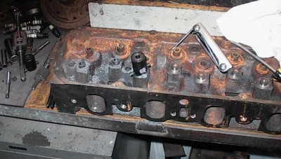
I had to set the heads up for screw-in studs and guide plates. Crane makes a
DIY kit for that, so I borrowed one. Shortly after I wished I'd used a seat
and guide machine. You use a big cutter with a pilot, a 3/4-hp low speed
drill, and lots of sweat to cut the rocker stands down.
An Allen bolt and sleeve form the pilot.
The pilot is the correct length, so when you bottom the cutter out on the
pilot, the stands are cut down the proper amount. Then you check with
calipers to make sure.
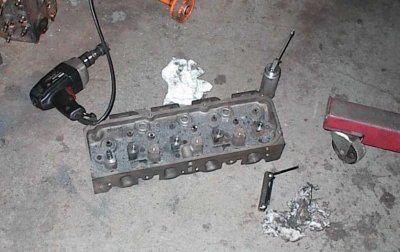
Now you clamp the hardened drill guide on and tap drill for a 7/16-14
thread...
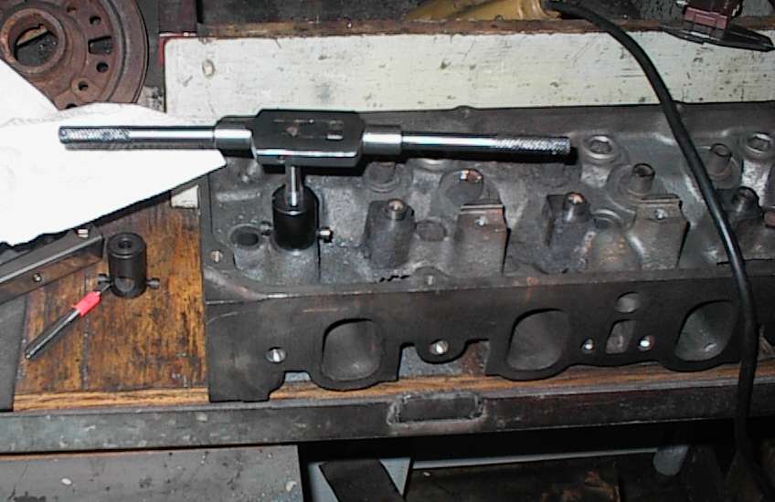
...and then you use the hardened tap guide to tap the hole. The remains of
the raised ring and any other projections are knocked off with a hammer and
chisel and the boss is filed flat. I thought I was going to save some time by
using the Crane kit, but it was almost as much fun as drilling a hole in your
head to let the evil spirits out.
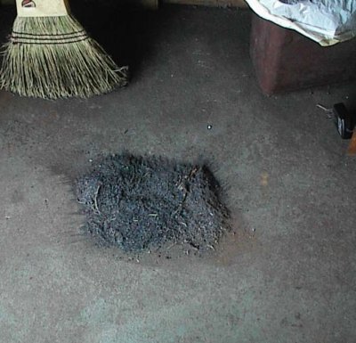
Probably 75% of the iron that was machined off the stands. The picture
doesn't lie; that's a big honking pile of chips.
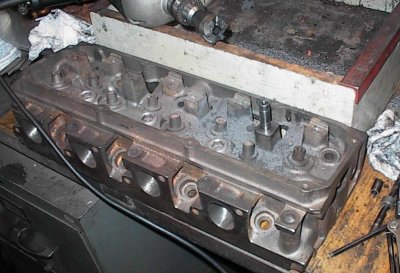
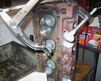
Fully machined and ready to assemble. I did a lot of bowl work, polished the
chambers and exhaust ports, plunge-cut the chambers to unshroud the valves,
opened the exhaust bowls up for 1.71" 4V exhaust valves, did a bunch of bowl
work and guide boss reduction, machined the deck, intake, and exhaust surfaces
flat, and various minor operations before shooting the heads with Rust-Oleum
primer. I left the intake ports alone, other than the bowls.
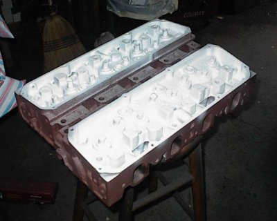
White VHT engine paint, just for looks.
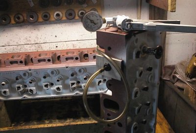
Lightweight test spring and vacuum gauge showing valve seal. I made my own
foam-backed vacuum plate, but you can buy them from tool supply places now.
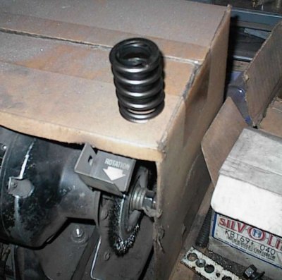
The springs had some sharp edges where they were square-wound on the ends. I
dressed them on the belt sander and smoothed them with the wire wheel. This
will keep them from gouging the titanium retainers.
They make all kinds of spring shims. These were originally for a Ford 3.8 V6
with aluminum heads, and form a sort of cup at the spring base. I bored them
on the lathe to fit the Cleveland heads. These go on a few of the spring
seats where the springs aren't completely supported, to prevent the springs
from trying to unwind down the side of the base.
Assembly. Taped-on natural organic composite (plywood) keeps the tool from
marring the ceramic coating on the valve heads.
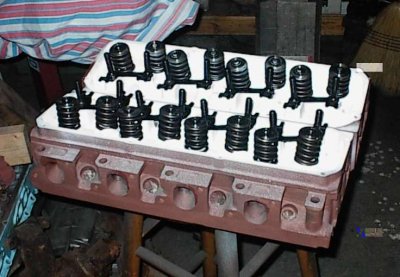
And here they are! Lots of machine work to get to this point.
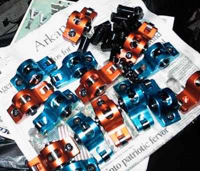
Roller rockers and bits after being washed in solvent. You'd be surprised at
the dirt and grit that come pre-installed on brand new, shrink wrapped parts.
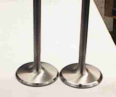
20 degree back-cut on intake valves enhances low-lift flow. The exhaust
valves were modified similarly.
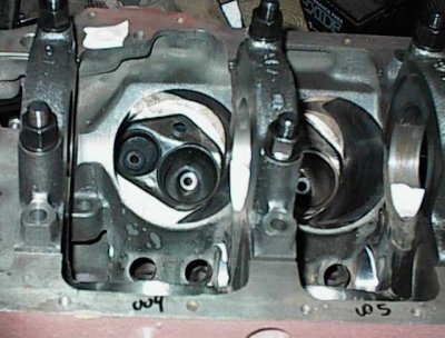
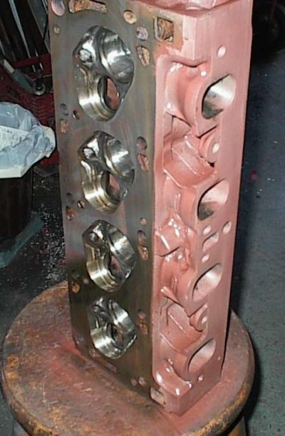
Here's a shot of the chamber alignment on the block. Even though the block is
.040-over, the chambers overhang the block slightly. Now I know lots of
engines do that, but I was sure surprised the first time I checked. Note the
large amounts of quench area with the closed chambers.
Assembly:
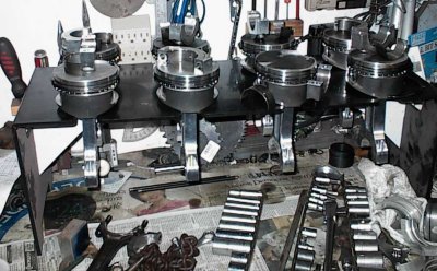
Plastic stand lets me assemble pistons, rings, etc. in order so I can just
pop them into the block. Of course, the rings have already been file-fit, the
rod side clearance adjusted, the rod bearing clearance checked, and all those
other niggling details taken care of.
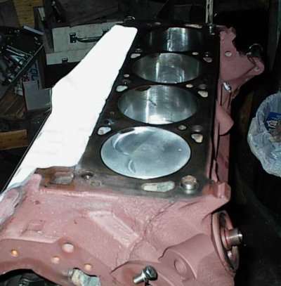
Putting the pistons in. The notch in the top of the block aligns with the
cut-away part of the intake valve relief. This is all factory stuff; even
some of the 2V engines come like this. The cutaways are to enhance mid-lift
air flow, not for valve clearance.
Deck height is zero.
Checking rod side clearance again. The aluminum rods have serrated caps. The
caps are free to float left to right, so you have to check clearance between
the shanks. You also have to make sure the rods are standing perpendicular to
the crank; there's enough float in the pistons and small ends for them to get
cocked enough to throw the measurements off, believe it or not.
Using lots of feeler gauges to wedge the rods against the crank cheeks to keep
the caps in alignment to torque the bolts. Otherwise, tightening the caps
will cause them to slide slightly, affecting the side clearance.
Milodon stud kit goes on 1/2" bolts only. The 3/8" bolts are just for show,
as far as I know. The Milodon studs didn't come with torque specs, so I
called Milodon - you torque them to the same value as stock, even though
they're fine thread. ARP studs use a lower-than-stock value. Kinda pretty in
there, isn't it?
The starter indent and the #4 rod are close, but clear by .080" or so.
Adjusting the valves. Run the polylocks down until the plunger in the lifter
loses contact with the snap ring, zero the dial indicator, and go down another
.030" for correct preload.
Before I got to this point, the guide plates had to be scooted left or right
with a brass hammer after loosening the studs slightly, to align the rocker
tips properly on the ends of the valve stems. I had to remove about half the
plates and slot the holes some more with a die grinder to get adequate
alignment. At least I didn't have to cut the plates, adjust them
individually, and weld them back together - sometimes you have to do that with
a Cleveland, and it's okay, but you have to pull the whole thing back down
again and clean all the weld spatter out of everything. Unless you own one of
those fancy TIG welders, which I lust for...
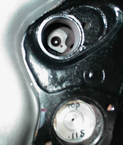
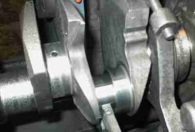
The flash obscures things a bit, but if you look down the bore at the wristpin
area, you'll see the connecting rod lines up almost exactly in the middle of
the pin bosses. This is normal for a Ford; some brands of engine offset the
rods under the piston enough to hit a boss if you're not careful. This is
another thing you have to check for when mix-and-matching parts.
The Cleveland carries its cam up high; there was plenty of cam/rod clearance
even with the 3.7" stroke and bulky aluminum rods.
Thoroughly coat the cam with the special moly lube before installation. I
also dumped in a bottle of GM Engine Oil Supplement for the initial run-in.
The EOS is a high pressure additive designed for new engines. Either would
do, but paranoia is good. If a flat tappet cam makes it through the initial
run-in okay it'll last a long time.
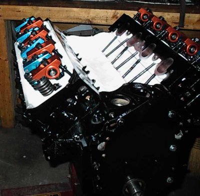
Gratuitous trophy shot of the long block - it took a long time to get here.
Weird mottled look to pushrods seems to be an artefact of the flash; they're
actually shiny black! Lifters are still dry, there's not full lift to the
valvetrain yet.
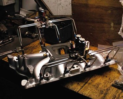
The Weiand X-Celerator is, from various dyno tests, the best off-the-shelf
intake for the 2V heads. This one had some welding done to take NOS Fogger
nozzles, then got powder coated. The mods and the stainless steel nitrous
tubing were done by a shop in a nearby town; very nice work.
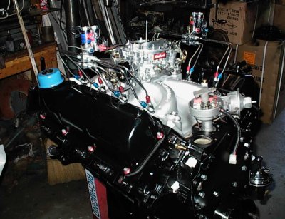
Another trophy shot. I ran an old pair of steel valve covers through the hot
tank and slapped them on just to fire it up. I was surprised that they
cleared the roller rockers with no trouble at all; I was expecting to have to
stack gaskets under them or do some hammer work.
Fire Up:
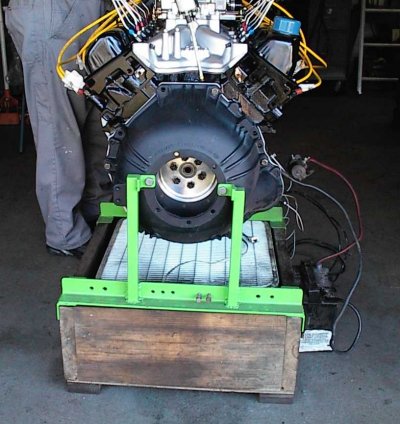
My little run stand with the Ford brackets. The bellhousing is there because
the Fords attach the starter to the bellhousing, not the block.
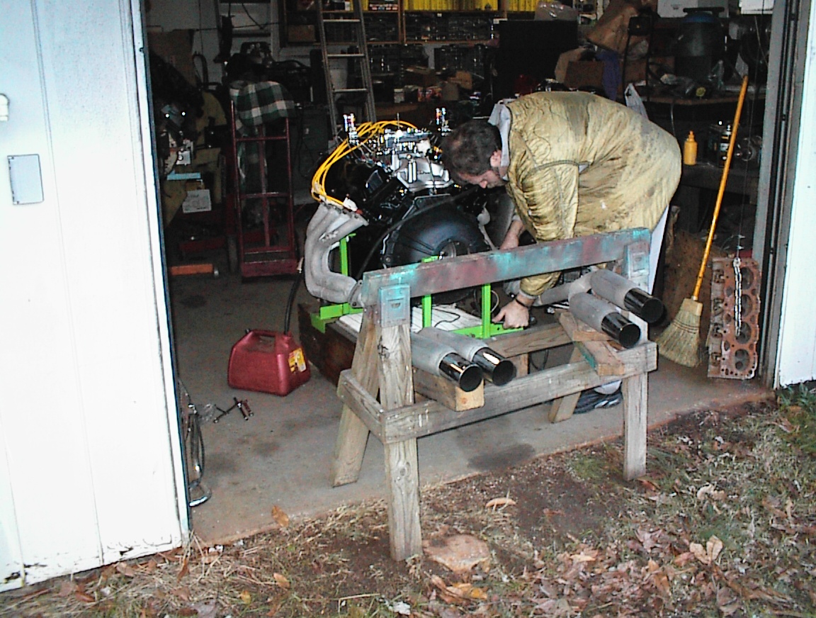
That's an entire Pantera exhaust system - headers, 18" of pipe, and ganged
glasspacks that haven't had any fiberglass since the Ford Administration. We
managed to twist and turn them enough to support them with the sawhorse.
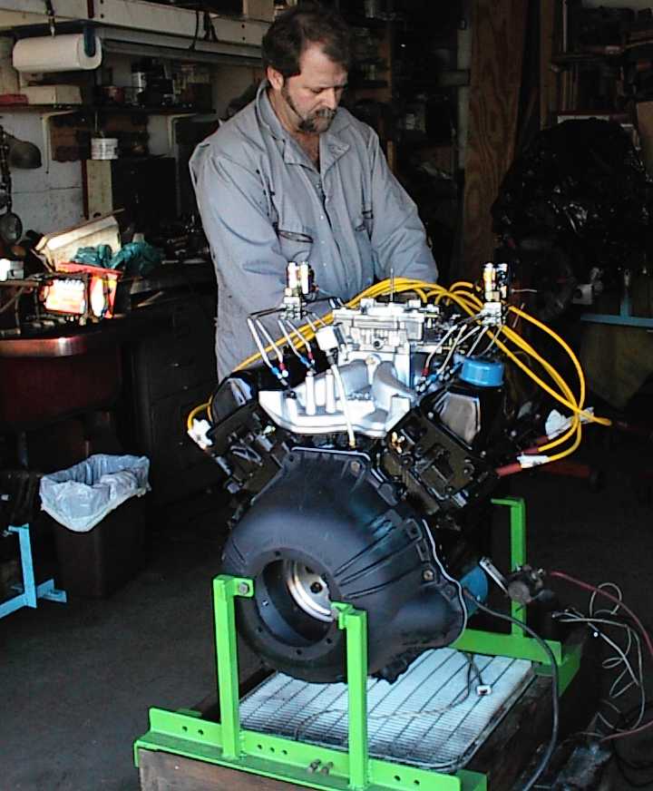
Alex is wiring up the distributor. We're just about ready to fire it up; it's
already been filled with oil and primed. The white doohickey on the long
stalk behind the intake is a VDO oil pressure gauge.
The battery was too low for the electronic ignition to work. It had been a
long day, so Alex went on home and I put the battery on the charger. The next
morning I went out and it fired right up, so I attached all the radiator
hoses, filled it with water, and ran it. The thing sounded gooood.
The lightened crank, aluminum rods, featherweight pistons, and aluminum
flywheel made the throttle response instant. I ran it for about half an hour,
ten minutes at a time. Did I mentioned it sounded good? A beautiful hot rod
lope at idle and a wail to make your hackles rise when you revved it up. The
sound echoed off the back of the house, and after a few minutes neighborhood
kids were hanging on the fence to see what all the commotion was. The
throttle was like a volume control.
Alex arrived a while later and I fired it back up. This time it sounded a
little ragged at idle. I looked over at the oil pressure gauge, which said
zero. Hmm, had 70 PSI before. I checked the gauge with shop air. Worked
fine. DAMN Well, this is why we're running it in on the stand
first...
Part 2