Author: Dave Williams; dlwilliams=aristotle=net
I've owned my trusty 1984 Mazda B2000 pickup since 1990 or so. The stock four cylinder engine was rated at 72 horsepower, and they were probably optimistic. It was slow to start with; when the 55mph speed limit was repealed, it was actually dangerous on the freeway, since its top speed was only about 65 unless the road was level and there was no wind. But it got 35 miles to the gallon, and you can put up with a lot for that.
I was originally going to swap a Buick V6 in. I had one all built up, and when the Mazda engine finally let go, I tried to drop it in, but the frame rails are narrower than the Buick's bellhousing flange. Oops.
I looked at trying to use an FWD block and a different transmission, but there was so much stuff different that I couldn't scavenge much off my old one - plus I would still have had to build custom exhaust manifolds to clear the A-arms.
I was checking out the 60 degree Chevy V6s when Sean Korb offered me a running 2.5 Chevy from an S-10 pickup, complete with T-5 five speed, alternator, and so forth, if I'd come pick it up. I couldn't pass up a deal like that, so I drove to North Carolina and got it.
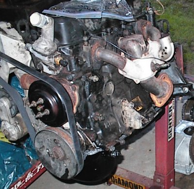 This is the engine after being cleaned up and with the modified oil pan.
Unbenownst to me, the engine had been full of oil when we lifted it into the
back of my station wagon, flipped it on its side, dragged it forward against
the back seat, and lashed it in place. And then it got tipped over and
dragged back out 850 miles later, without losing a drop of oil! It had never
occurred to me to check.
This is the engine after being cleaned up and with the modified oil pan.
Unbenownst to me, the engine had been full of oil when we lifted it into the
back of my station wagon, flipped it on its side, dragged it forward against
the back seat, and lashed it in place. And then it got tipped over and
dragged back out 850 miles later, without losing a drop of oil! It had never
occurred to me to check.
Of course, one possible reason why the oil didn't drool out all over my beige carpet was because it had turned into black Jell-O. However many miles were on the engine, it was probably the same oil it left Detroit with. I pulled the valve cover, manifold, and pan, then used Gunk, carburetor cleaner, and the pressure washer to blast the crud out.
This is a later picture, all cleaned up. I've deleted the idler pulley Chevy
used, and found a serpentine belt that will work without it. This makes the
water pump turn backwards. I'll have to replace it with one from an inline
six; it bolts up and turns the correct direction.
 As far as I could tell, all RWD and FWD 2.5s had exactly the same rear sump
oil pan. Unfortunately, the B2000 needed a front sump pan. Here, I've
measured up from the pan rail, made some marks to make a level cut, and run
some tape so I could see where to cut. Masking tape is a very useful tool!
As far as I could tell, all RWD and FWD 2.5s had exactly the same rear sump
oil pan. Unfortunately, the B2000 needed a front sump pan. Here, I've
measured up from the pan rail, made some marks to make a level cut, and run
some tape so I could see where to cut. Masking tape is a very useful tool!
 I annoyed the neighbors with the air cutoff tool for ten or fifteen minutes.
The pan was fairly thick steel.
I annoyed the neighbors with the air cutoff tool for ten or fifteen minutes.
The pan was fairly thick steel.
 The near hole is the back, where I cut the sump off. I managed to turn it 180
degrees and line it up fairly well with the front, then cut a hole up there,
too, and tack welded the sump into place.
The near hole is the back, where I cut the sump off. I managed to turn it 180
degrees and line it up fairly well with the front, then cut a hole up there,
too, and tack welded the sump into place.
 Here's another shot. Not pretty, but it's lining up nicely.
 I just happened to have a junk block on hand to use as a welding jig.
This was supposed to prevent the pan from warping, ha, haa...
I just happened to have a junk block on hand to use as a welding jig.
This was supposed to prevent the pan from warping, ha, haa...
 A sheet metal patch over the gap in front, and then, finding I didn't have a
piece of metal big enough to cover the back, I welded three strips together.
Hey, more opportunity to leak, right?
A sheet metal patch over the gap in front, and then, finding I didn't have a
piece of metal big enough to cover the back, I welded three strips together.
Hey, more opportunity to leak, right?
The metal GM used for the pan welded beautifully, though...
 When I unbolted the pan, it had a dramatic diagonal twist. I thought about
the problem for a couple of days, then said "what the heck, it already has
ten feet of weld," and made a diagonal cut with the cutoff wheel. When I
bolted the pan back down, the slice opened up half an inch. Then I welded a
strip across it.
When I unbolted the pan, it had a dramatic diagonal twist. I thought about
the problem for a couple of days, then said "what the heck, it already has
ten feet of weld," and made a diagonal cut with the cutoff wheel. When I
bolted the pan back down, the slice opened up half an inch. Then I welded a
strip across it.
In this shot, I've epoxied along the insides of the welds, hoping to avoid the
Colander Effect that plagues chopped and channeled oil pans.
 Mr. Holesaw made an opening for a large pipe fitting. This will be the
turbocharger oil return, when I get the turbo on. It's easier to do all this
now instead of later.
Mr. Holesaw made an opening for a large pipe fitting. This will be the
turbocharger oil return, when I get the turbo on. It's easier to do all this
now instead of later.
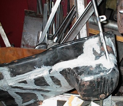
 Finished outside. Yeah, it looks cobby, but it seems to be oil tight.
 Paranoia; I epoxied the outsides of the welds too. I'm not quite finished
yet...
Paranoia; I epoxied the outsides of the welds too. I'm not quite finished
yet...
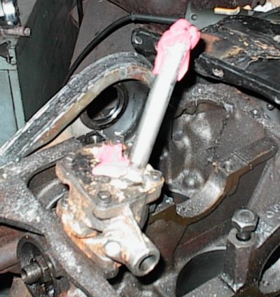
 ...because the dipstick has to be mounted. I used some 3/8" steel tubing,
larger than most dipstick tubes, because it was on hand.
...because the dipstick has to be mounted. I used some 3/8" steel tubing,
larger than most dipstick tubes, because it was on hand.
 Tube welded in. The tab midway down anchors it to a boss on the side of the
block. I chamfered the mouth of the tube on the lathe. It sticks out at an
odd angle, but it clears all the accessories.
Tube welded in. The tab midway down anchors it to a boss on the side of the
block. I chamfered the mouth of the tube on the lathe. It sticks out at an
odd angle, but it clears all the accessories.
You can also see where I got even more paranoid and epoxied the whole inside
of the pan into one seamless oil barrier.
 A shot from another angle.
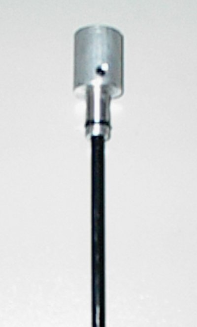 More headliner rod for the dipstick, a piece of 3/4" aluminum bar stock for
the knob, grooved for an O-ring and drilled and tapped for a set screw.
Remember, there's no kill like an overkill...
More headliner rod for the dipstick, a piece of 3/4" aluminum bar stock for
the knob, grooved for an O-ring and drilled and tapped for a set screw.
Remember, there's no kill like an overkill...
 Then, since there's no kill like an overkill, I laid in three heavy coats of
epoxy paint...
Then, since there's no kill like an overkill, I laid in three heavy coats of
epoxy paint...
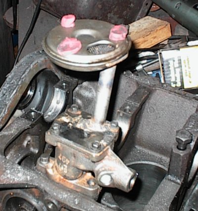
 And here it is on the engine. It was a trick to position the dipstick to
allow access to the oil filter, clear all the bolt heads and brackets, and
still miss the alternator.
And here it is on the engine. It was a trick to position the dipstick to
allow access to the oil filter, clear all the bolt heads and brackets, and
still miss the alternator.
 Since all 2.5 pickup tubes ran straight back, with the oil pump being in front
and the sump at the rear, the pump was designed to make that easy.
Unfortunately, the inlet boss was now 1/32" from the wall of the new front
sump, no room to mount a pickup tube.
Since all 2.5 pickup tubes ran straight back, with the oil pump being in front
and the sump at the rear, the pump was designed to make that easy.
Unfortunately, the inlet boss was now 1/32" from the wall of the new front
sump, no room to mount a pickup tube.
I made a plug on the lathe and blocked off the stock oil inlet.
 I examined the wear marks on the inside of the cover plate, then drilled a
9/16" hole in the appropriate location. Then I eyeballed the length of the
pickup pipe and tack welded it to the cover. A little clay at the end, a
couple more cuts to shorten it and get the angle right...
I examined the wear marks on the inside of the cover plate, then drilled a
9/16" hole in the appropriate location. Then I eyeballed the length of the
pickup pipe and tack welded it to the cover. A little clay at the end, a
couple more cuts to shorten it and get the angle right...
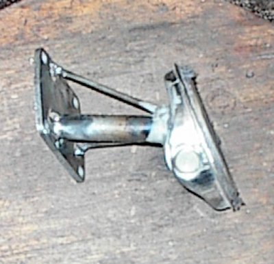
 The pickup tube is welded firmly to the cover. I sawed the stock pickup end
off its tube and tacked it to the new tube, into a hole I drilled into the
top. The stock inlet was from the side. Clay shows its relation to the floor
of the pan.
The pickup tube is welded firmly to the cover. I sawed the stock pickup end
off its tube and tacked it to the new tube, into a hole I drilled into the
top. The stock inlet was from the side. Clay shows its relation to the floor
of the pan.
 I ground away the old tube, which looked like it might block flow to my new
one, and then ground a nice flare on the inlet of the new tube.
I ground away the old tube, which looked like it might block flow to my new
one, and then ground a nice flare on the inlet of the new tube.
 A little epoxy to keep the air leaks away... the rods are from some old
headliner bows. I figured they'd stop any vibrations that might try to crack
the welds.
A little epoxy to keep the air leaks away... the rods are from some old
headliner bows. I figured they'd stop any vibrations that might try to crack
the welds.
 Now some hardware store screen. Nobody sells steel screen around here any
more, so I used nylon.
Now some hardware store screen. Nobody sells steel screen around here any
more, so I used nylon.
 Install the screen, reinstall the cover, hammer all the edges over, trim.
 The finished cover. The old inlet hole got a press-in plug, made on the
lathe. The cover had warped a bit with all of the welding, which was
expected. I used the belt sander to make it flat again.
The finished cover. The old inlet hole got a press-in plug, made on the
lathe. The cover had warped a bit with all of the welding, which was
expected. I used the belt sander to make it flat again.
 The finished oil pump assembly, ready to be installed on the engine.
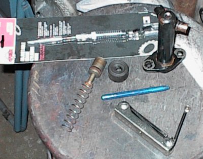 I had three slave cylinders, all frozen solid with rust. I drilled and tapped
a 1/8" NPT hole in the end of this one, drove it apart with a rod, and honed
it back smooth with a wheel cylinder hone.
I had three slave cylinders, all frozen solid with rust. I drilled and tapped
a 1/8" NPT hole in the end of this one, drove it apart with a rod, and honed
it back smooth with a wheel cylinder hone.
 The rest of the goodies from Sean - T-5 bellhousing, T-5 transmission,
flywheel, new pressure plate, disc, and throwout bearing.
The rest of the goodies from Sean - T-5 bellhousing, T-5 transmission,
flywheel, new pressure plate, disc, and throwout bearing.
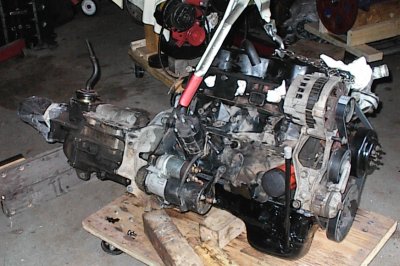 Complete engine, ready to go, with rebuilt starter and all accessories.
Since the engine from Sean was running, I decided to leave it alone and get it in the truck ASAP. The engines from Kenney were a different story.
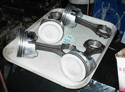
The 2.5 is an interesting engine. Big bore, short stroke - 4 x 3 inches. It's like half of a Ford 302. The connecting rods are 6" long, for a 2:1 rod ratio. It's relatively light and small, being a pushrod design. Two gear cam drive. The cylinder head looks like something from the 1940s - bean-shaped chambers, vertical valves, and horrible intake ports - and it has "long" and "short" ports like a big block Chevy! But lots of quench, and the valve sizes weren't too bad.
About this time I acquired a nice KKK turbo and wastegate from an Audi, the right size to work with a 2.5. A little porting in the cylinder head, and the turbo will make up for its other deficiencies. I kind of like these little engines.
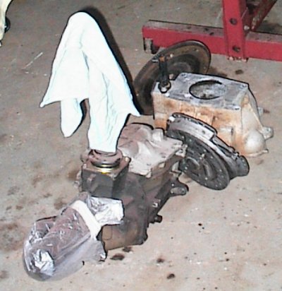
 The first of the dead engines. This one had maybe 5000 miles after Kenney had
rebuilt it. The owner of the truck then swapped in a V8 and dumped the old
driveline off at Kenney's. It then sat out in the rain, filled with water,
and the bores pitted too badly to re-use the block.
The first of the dead engines. This one had maybe 5000 miles after Kenney had
rebuilt it. The owner of the truck then swapped in a V8 and dumped the old
driveline off at Kenney's. It then sat out in the rain, filled with water,
and the bores pitted too badly to re-use the block.
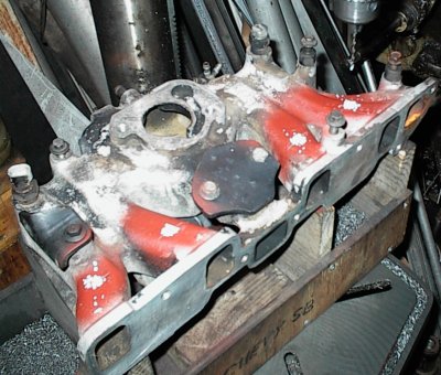
 The second engine had no cylinder head, had also sat out in the rain and
froze, but it was just a cracked water jacket. I welded the crack and we
bored it .040-over to take the pistons from the other engine.
The second engine had no cylinder head, had also sat out in the rain and
froze, but it was just a cracked water jacket. I welded the crack and we
bored it .040-over to take the pistons from the other engine.
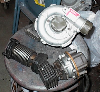 The Audi turbo. Most OEM turbos use integral wastegates; this one uses a
fancy external wastegate.
The Audi turbo. Most OEM turbos use integral wastegates; this one uses a
fancy external wastegate.
 The 2.5, like most large fours, is known for being rumbly and noisy. Here's
the main reason why - the crankshaft is only partially counterweighted. This
means there are strong bending couples across it when it's running, which are
transmitted to the block as noise.
The 2.5, like most large fours, is known for being rumbly and noisy. Here's
the main reason why - the crankshaft is only partially counterweighted. This
means there are strong bending couples across it when it's running, which are
transmitted to the block as noise.
The Chevy Power manual from GM has a section on building their old OHC fours,
which had nearly identical cranks. Chevy recommended attaching big bars of
heavy metal to the counterweights to help the internal stress problem.
 This was a spare crank, worn slightly, so I decided to donate it to science.
Mr. Bandsaw is assisting me again.
This was a spare crank, worn slightly, so I decided to donate it to science.
Mr. Bandsaw is assisting me again.
 It's difficult to balance a crank for an inline engine. The balance machine
can show perfect balance - like with the stock 2.5 crank - but it can only
measure the balance end-to-end. There's no way for it to check the internal
couples. So I needed to find out what those internal couples were.
It's difficult to balance a crank for an inline engine. The balance machine
can show perfect balance - like with the stock 2.5 crank - but it can only
measure the balance end-to-end. There's no way for it to check the internal
couples. So I needed to find out what those internal couples were.
 The front and rear quarters, like so...
 ...and then welded...
 The center throws, like so.
 The little matchbox-sized counterweights are clearly not enough to balance a
pair of 4" pistons on 6" rods.
The little matchbox-sized counterweights are clearly not enough to balance a
pair of 4" pistons on 6" rods.
 I made paper templates for cutting extra weights out of steel plate.
 3/8" and 3/4" steel plate counterweights.
 I masked and sandblasted the piston tops for thermal barrier coating.
 Steel tubing exhaust manifold. The stinger will be replaced with a U-tube to
the turbo.
Steel tubing exhaust manifold. The stinger will be replaced with a U-tube to
the turbo.
 One of the spare flywheels was very rusty and had to be resurfaced. I
ran it through the hot tank, sprayed some paint around the edge, and used
dividers and calipers to mark a series of evenly-spaced holes. You can just
barely make the marks out in this shot.
One of the spare flywheels was very rusty and had to be resurfaced. I
ran it through the hot tank, sprayed some paint around the edge, and used
dividers and calipers to mark a series of evenly-spaced holes. You can just
barely make the marks out in this shot.
 After center-punching the marks, I drilled small guide holes through the
flywheel.
After center-punching the marks, I drilled small guide holes through the
flywheel.
 Then I drilled 22 1" holes, a 5/8" hole, and a 3/4" hole through. The smaller
holes were a workaround for two balancing holes GM had already drilled, in
places where it made it impossible to use an ordinary 1" drill to eliminate
them, as the drill would intersect the original holes and walk.. I'll add a
couple of pocks later to even things up when I have it on the balancing
machine. The perimeter is the most effective place to remove weight. This
will smooth the torque vibration from the engine a bit, and make up for the
extra crankshaft weight. With the B2000's 3.63 rear axle ratio, I don't think
there will be any flywheel weight problems.
Then I drilled 22 1" holes, a 5/8" hole, and a 3/4" hole through. The smaller
holes were a workaround for two balancing holes GM had already drilled, in
places where it made it impossible to use an ordinary 1" drill to eliminate
them, as the drill would intersect the original holes and walk.. I'll add a
couple of pocks later to even things up when I have it on the balancing
machine. The perimeter is the most effective place to remove weight. This
will smooth the torque vibration from the engine a bit, and make up for the
extra crankshaft weight. With the B2000's 3.63 rear axle ratio, I don't think
there will be any flywheel weight problems.
 Inexplicably dark shot of flywheel after surfacing. Dark object is ball hone,
used to smooth and radius the drilled holes.
Inexplicably dark shot of flywheel after surfacing. Dark object is ball hone,
used to smooth and radius the drilled holes.
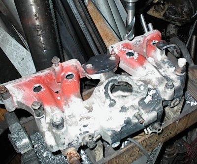
 I may build a better intake manifold later. To start with, I'm modifying
the spare intake for port fuel injectors and water injection nozzles in the
plenum area. Here I'm drilling pilot holes for the port injectors.
I may build a better intake manifold later. To start with, I'm modifying
the spare intake for port fuel injectors and water injection nozzles in the
plenum area. Here I'm drilling pilot holes for the port injectors.
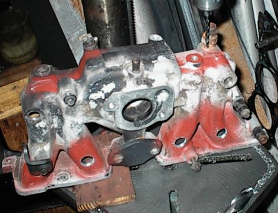
 Now I've drilled 3/4" holes for the injector bungs.
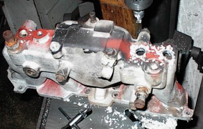
 Standing it on end for the water injector nozzle holes.
 Working on the nozzle holes...
 A couple of nozzle bungs. I'm using brass Bosch K-Jetronic
fuel injection nozzles for the water injection. They will spray right down
each intake runner.
A couple of nozzle bungs. I'm using brass Bosch K-Jetronic
fuel injection nozzles for the water injection. They will spray right down
each intake runner.