This page: www.bacomatic.org/~dw/302strok/crank.htm
Main page: http://www.bacomatic.org/~dw/index.htm
Last Updated: 16 Jul 2003
How To Make a 347-357 Cubic Inch 302 Ford Stroker
How To Make a 347-357 Cubic Inch 302 Ford Stroker
Here it comes, over 640Kb of pictures. Time for a coffee break or something.
These pictures span over four years of low-priority tinkering. Specialty
shops were doing it before I started, but I had to find out all the gotchas on
my own. By the time I was done you could buy custom cast 3.4 and 3.5 inch
stroke cranks from the aftermarket; it's hardly worth carving a Cleveland
crank when you can buy the stuff off the shelf. But it was a nice project all
the same.
The order is sort of odd, but more or less chronological. I didn't do all of
it at once; there were several trips back and forth between the crank grinder,
lathe, and the angle grinder.
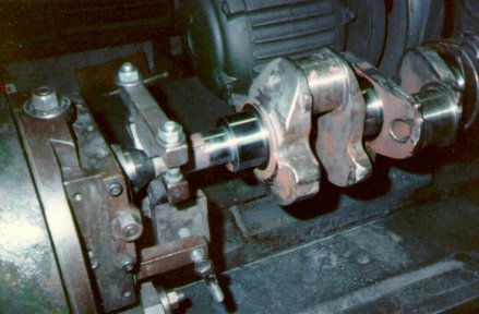
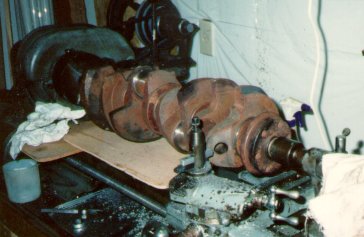 Getting ready for the first cuts on the rear counterweight. The 351C
crankshaft came from the junk iron pile behind a local engine shop. I mooched
it from them after hitting it with a tape measure and figuring it might be
possible to cram it into a 302. It turned out that was how all the "cast
crank" strokers were made in 1994, but I didn't know that then.
Getting ready for the first cuts on the rear counterweight. The 351C
crankshaft came from the junk iron pile behind a local engine shop. I mooched
it from them after hitting it with a tape measure and figuring it might be
possible to cram it into a 302. It turned out that was how all the "cast
crank" strokers were made in 1994, but I didn't know that then.
 Turning counterweights down on lathe, no grinding yet.
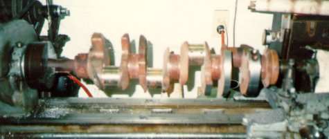
 Doing second rod journal on crank grinder. Rightmost is done. We're coming
down from 2.311" to 2.124". Yes, that's a lot of grinding.
Doing second rod journal on crank grinder. Rightmost is done. We're coming
down from 2.311" to 2.124". Yes, that's a lot of grinding.
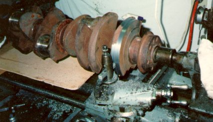
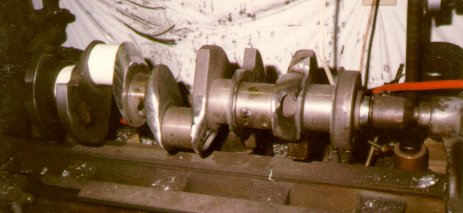
 Getting ready to profile counterweights. Crank has sat a few months in swamp
weather and rusted back up. Piston slams into counterweight at BDC; about 1-
1/2 inch of the counterweight has to come off, plus .060 or so clearance. You
can turn about 3/4 of an inch off on the lathe; then you have to use the
grinder to 'profile', or shape the counterweight so the piston will clear.
Getting ready to profile counterweights. Crank has sat a few months in swamp
weather and rusted back up. Piston slams into counterweight at BDC; about 1-
1/2 inch of the counterweight has to come off, plus .060 or so clearance. You
can turn about 3/4 of an inch off on the lathe; then you have to use the
grinder to 'profile', or shape the counterweight so the piston will clear.
 Working on rear counterweights. The 351C weights were too big
for the lathe carriage to pass underneath; I had to trim them
down close to 302 size before I could make a single pass along
the whole length of the crank. A bigger lathe would have made
things much easier.
Working on rear counterweights. The 351C weights were too big
for the lathe carriage to pass underneath; I had to trim them
down close to 302 size before I could make a single pass along
the whole length of the crank. A bigger lathe would have made
things much easier.
 Lightening rod throws and grinding excess metal away.
 Profiling the crankpins. They were nice and fat, lots of metal to take off.
By now I've ceased to worry about grit and dust in the lathe; it was
impossible to keep it clean. I took the whole machine apart, cleaned, and
oiled it when I was done. Now I have a bench and a cradle to hold a crank for
grinding, and the poor old lathe stays clean.
Profiling the crankpins. They were nice and fat, lots of metal to take off.
By now I've ceased to worry about grit and dust in the lathe; it was
impossible to keep it clean. I took the whole machine apart, cleaned, and
oiled it when I was done. Now I have a bench and a cradle to hold a crank for
grinding, and the poor old lathe stays clean.
 Cutting mains. 1/2" has to come off here, and the center
journal has to be widened. For some reason the 351C has a narrower
center main than a 302!
Cutting mains. 1/2" has to come off here, and the center
journal has to be widened. For some reason the 351C has a narrower
center main than a 302!
 #1 main done, "snout ring" behind the cam gear has been trimmed off. This had
to be redone; it turned out a lot more metal had to come off the 351C snout to
get the right distance from the center main to the timing sprocket so the
sprockets would line up. I made a custom measuring tool to guage it while on
the crank grinder.
#1 main done, "snout ring" behind the cam gear has been trimmed off. This had
to be redone; it turned out a lot more metal had to come off the 351C snout to
get the right distance from the center main to the timing sprocket so the
sprockets would line up. I made a custom measuring tool to guage it while on
the crank grinder.
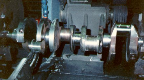
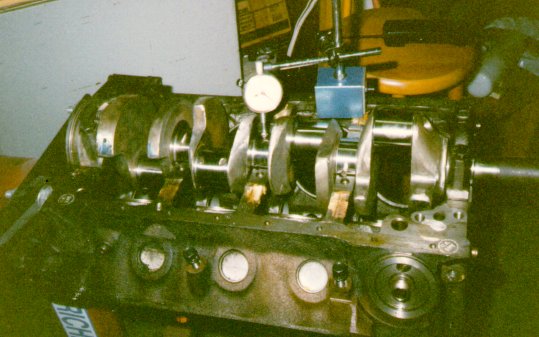 Checking to make sure it's still straight. Note profiling on crankpins.
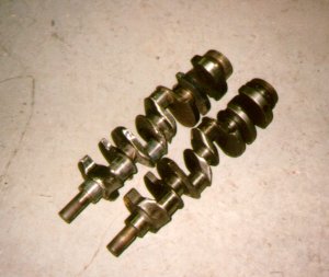
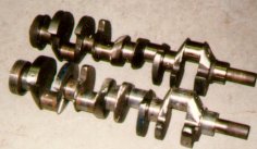 351C, 3.5" stroke crank cut down for a 302, vs. a lightened
302 crank. Not much visible difference. 351C in foreground
The half inch stroke difference is hard to spot, eh?
351C, 3.5" stroke crank cut down for a 302, vs. a lightened
302 crank. Not much visible difference. 351C in foreground
The half inch stroke difference is hard to spot, eh?
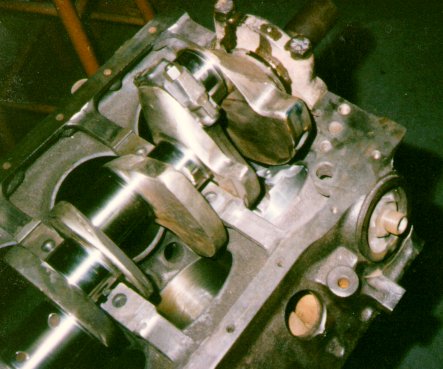
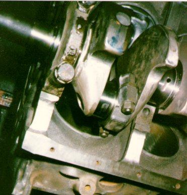 Checking fit in block. Rod bolt hits bottom of skirt, which has to be ground
away for clearance. You can't see it here, but the front of the #1
counterweight has been ground for clearance for the oil pump drive rod.
There's a raised 'disc' of metal on the front of Cleveland #1 counterweight;
you need to cut it down flat with the rest of the weight. I used my angle
grinder, but a the lathe or crank grinder will work just as well.
Checking fit in block. Rod bolt hits bottom of skirt, which has to be ground
away for clearance. You can't see it here, but the front of the #1
counterweight has been ground for clearance for the oil pump drive rod.
There's a raised 'disc' of metal on the front of Cleveland #1 counterweight;
you need to cut it down flat with the rest of the weight. I used my angle
grinder, but a the lathe or crank grinder will work just as well.
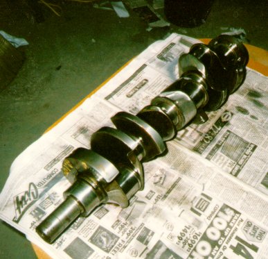 Close to done now. Many hours of work to get here. I thought I was done, but
I wound up having to reduce the length of the snout a bit. Just one of
the many minor gotchas...
Close to done now. Many hours of work to get here. I thought I was done, but
I wound up having to reduce the length of the snout a bit. Just one of
the many minor gotchas...
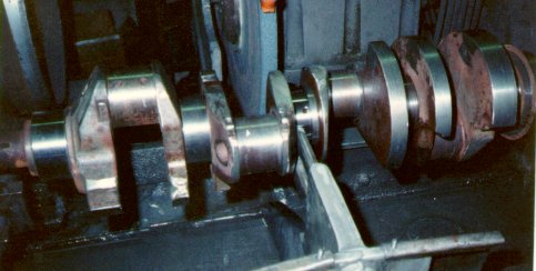
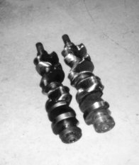
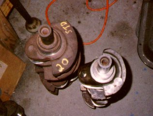 A more dramatic shot. The left hand crank is a stock 351C. Right hand is the
modified 351C. The balance took two slugs of heavy metal in the front even
with a 50oz 5.0 damper and flexplate. The rear didn't need anything. After I
got my own balance machine, I balanced a similar stroker for another shop.
Instead of drilling and pressing heavy metal in, I shaped a steel block and
welded/bolted it to the side of the counterweight. The block was faster to do
and cheaper than heavy metal, and worked great.
A more dramatic shot. The left hand crank is a stock 351C. Right hand is the
modified 351C. The balance took two slugs of heavy metal in the front even
with a 50oz 5.0 damper and flexplate. The rear didn't need anything. After I
got my own balance machine, I balanced a similar stroker for another shop.
Instead of drilling and pressing heavy metal in, I shaped a steel block and
welded/bolted it to the side of the counterweight. The block was faster to do
and cheaper than heavy metal, and worked great.
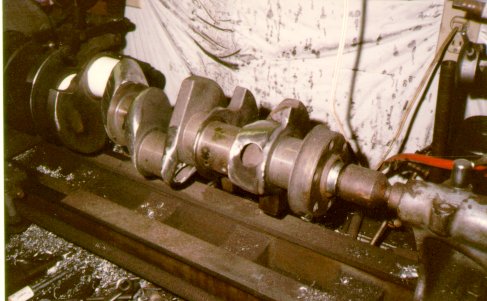
 Checking clearances yet again. Part of the flange by the oil pump boss is
marked for trimming. This is actually a very early photo as you can tell by
the squarish rod throws; still plenty of grinding to go.
Checking clearances yet again. Part of the flange by the oil pump boss is
marked for trimming. This is actually a very early photo as you can tell by
the squarish rod throws; still plenty of grinding to go.
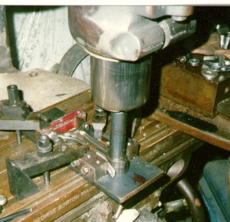 Mandrel in mill collet is lining up rod fixture prior to boring pin end
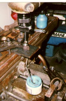 Boring the pin end. There's a hole in the steel plate below the rod; the
boring bar passes all the way through
Boring the pin end. There's a hole in the steel plate below the rod; the
boring bar passes all the way through
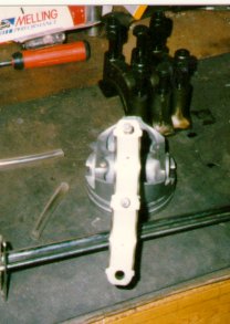 The 2300 rod bearings are lined up perfectly in the rod. This doesn't always
happen; some engines offset the bearings substantially to one side or randomly
locate a narrow bearing right or left.
The 2300 rod bearings are lined up perfectly in the rod. This doesn't always
happen; some engines offset the bearings substantially to one side or randomly
locate a narrow bearing right or left.
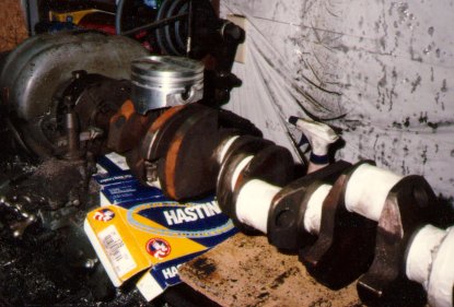
 Note how much of piston hangs out bottom of bore at BDC. Part of the wristpin
actually sticks out of the bottom of the bore. However, the connecting rod is
almost straight up and down at this point, so there's little to try to rock
the piston. It still looks frightening, but there are lots of strokers out
there with no troubles.
Note how much of piston hangs out bottom of bore at BDC. Part of the wristpin
actually sticks out of the bottom of the bore. However, the connecting rod is
almost straight up and down at this point, so there's little to try to rock
the piston. It still looks frightening, but there are lots of strokers out
there with no troubles.
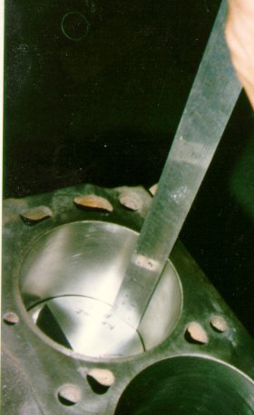 The ruler shows 3-1/2 inches; with the stock 4.00 bore, that's 351 cubic
inches from a 5.0 block. This is actually a 289 block; I was checking to see
if the clearancing needed to swing the crank and rods would be different.
It's about the same as a 5.0.
The ruler shows 3-1/2 inches; with the stock 4.00 bore, that's 351 cubic
inches from a 5.0 block. This is actually a 289 block; I was checking to see
if the clearancing needed to swing the crank and rods would be different.
It's about the same as a 5.0.
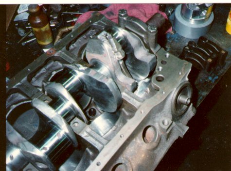
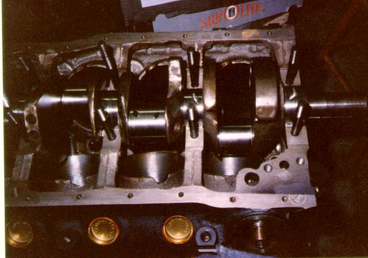 Here we are, the real McCoy. The once-junk crankshaft is going into an '87
roller 5.0 block. The complete long block with D0OE 351W heads went to a
Fordnatic in California. Note rod bolt cutouts in cylinder skirts.
Here we are, the real McCoy. The once-junk crankshaft is going into an '87
roller 5.0 block. The complete long block with D0OE 351W heads went to a
Fordnatic in California. Note rod bolt cutouts in cylinder skirts.