Mark Bauer's 351X
This page: www.bacomatic.org/~dw/351x/351x.htm
Main page:
http://www.bacomatic.org/~dw/index.htm
Last Updated: 06 Jul 2005
Author: Dave Williams; dlwilliams=aristotle=net
I started building this engine in 1991 for a customer who wanted something a
little zippier than the usual 289 or 302 for his Cobra kit car, but didn't
want to go to a big block. 1991 was during the dark ages of Ford performance;
other than the $2500 J302s from Ford there wasn't much in the way of Windsor
heads.
After thinking about things, I decided to go with a pair of 351 Cleveland
heads. I was starting on the intake adapter plates when I found out B&A
Performance made an intake manifold for just this conversion. It turned out I
wasn't breaking new ground after all. [grin] The B&A intake was expensive
but saved a lot of work, so I bought it, a set of special Federal Mogul domed
conversion pistons they were selling, and had them do the water mods on my
351C-2V heads and set them up for screw in studs.
B&A furnished a lot of information about the Cleveland conversions. When I
visited them in 1991 (they were only a few hours away!) they had an engine
similar to mine that made 445hp; same compression, same solid lifter cam I
planned to use, just a hair more stroke. The Guess-O-Meter says my 351 inch
engine might make around 400hp. That's not bad for a normally aspirated,
streetable 351!
The magazines like to call them "Clevors", which sounds like the name of some
hillbilly with no teeth. I call it a "351X", X standing for "cross", as in
crossbreed.
I had the short block ready to assemble, the intake, and the partially
machined heads when the buyer defaulted. At the time I had about $1500 in
parts and machine work, but even though it was for sale for ten years I never
got any serious enquiries. After the Windsor aftermarket took off there
wasn't any interest in the "old technology" Cleveland stuff, so the mocked-up
partial engine assembly engine sat on its engine stand in the living room
until 1998, when I hauled it out to my workshop, which I didn't have when the
engine was started. My wife used to hang laundry on it.
Several times I thought about doing something with the engine, but I don't own
a car that it would fit into, other than Thunder, which has a perfectly good
Oldsmobile engine in it and a brand new 455 waiting for round tuits. Then,
for some weird reason, in early 2001 one of the guys on Fordnatics had a nice
street roller cam at a reasonable price. I bought it, since I had a brand new
set of solid rollers on the shelf. I kicked out a few bucks for 7/16" screw
in studs, stepped guide plates, etc. I had some compatible valve springs on
hand, and a new oil pump, and... things sort of took off when I made a deal
for some used but serviceable titanium valves.
Eventually Mark Bauer up in Michigan decided the 351X would look very nice
between the shock towers of his '68 Mustang. Soon I will have more pictures
of the engine build and the completed engine.

Special Sealed Power conversion pistons - 351W pin height, 351C domes for 10:1
CR with 351C-2V heads.
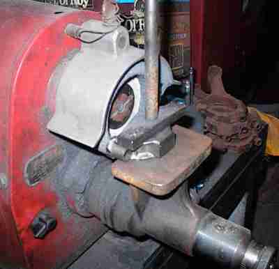
Cutting the rod caps. The shanks get cut too. You take a few thousandths off
to square them up (Ford uses an axe, I believe) and reduce the diameter of the
big end, which is usually too big to start with. The 351W rods don't give
much bearing crush, which is probably the real reason why the Windsors are
known to have rod troubles. I'll size them down to the minimum on the next
step.
I wanted to use Tech Line's CBC2 thermal barrier and TLML moly on the pistons,
so they had to be sandblasted to provide proper "tooth" for the coating to
hold on. The coatings are very slick and don't stick well, so you have to
have a rough surface for them to grab on to, sort of like a Teflon coated
frying pan.
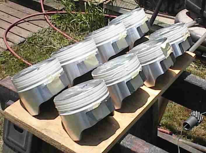
First you tape off the ring groove and pin holes, leaving the places you want
to sandblast (the decks and skirts) bare. Then you put on your plastic
poncho and face shield and fire up the sand blaster.
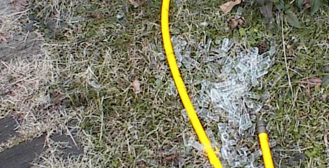
It would be nice if I had a sandblast cabinet. but I tell myself the sand
helps fill the low spots in the yard...
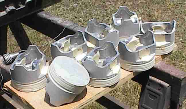
Here's what they look like after being sandblasted. There's sand all over the
back yard, in my hair, under my shirt, in my pockets, and down the crack of my
ass. The poncho only works so-so...
After a shower and clean clothes, I untaped the pistons, scrubbed them under
running water with a soft bristle brush to remove any embedded sand, and
rinsed them in acetone to remove any oil that might have come out of the shop
air line.
Here we are, masked off again. I'm shooting the moly first. You have to
handle the pistons carefully; the coatings don't like oil *at all*, even from
a fingerprint. They'll blister or lift if the surface isn't perfect.
First coat fogged on. You're only supposed to use just enough to color the
parts, but I tend to lay it on thicker than that. The excess wears off.
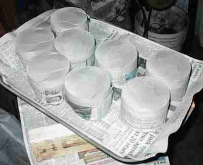
Here they are, coated and detaped. Now they get baked for an hour at 300F to
flash the solvent out of the moly.
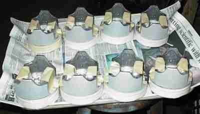
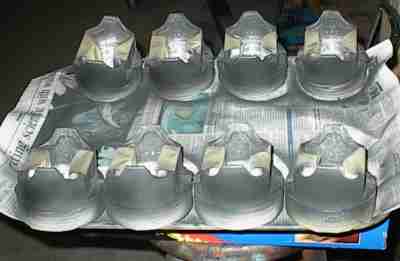
Masked yet again, with newspaper protecting the moly skirts. The second coat
of thermal barrier ceramic has just been sprayed; you can see where it's still
wet.
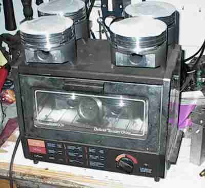
The little toaster oven only holds two pistons at a time. This is the second
pair starting on an hour at 350F.

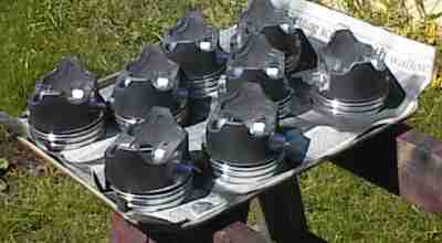
Finished piston. Symmetrical dome lets them be installed on either side; the
wristpins are offset for quiet operation. I had a pair of Australian closed-
chamber 2V heads on hand and the pistons fit those chambers, too.
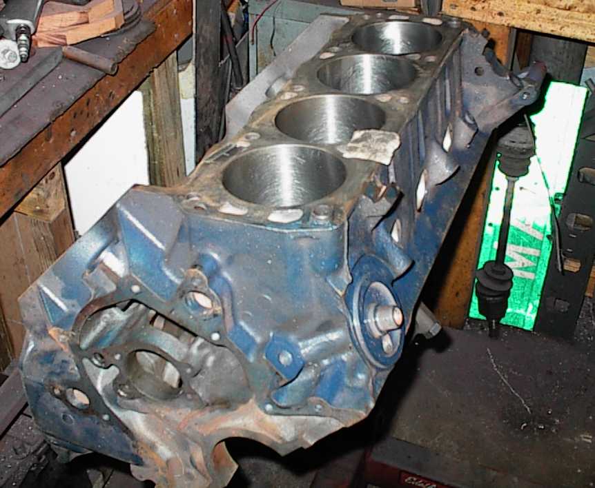
This was one of the last engines I built before I started buying my own tools.
The shop that bored and honed the block left it about .002" undersize; it
would probably have galled the pistons soon after startup.
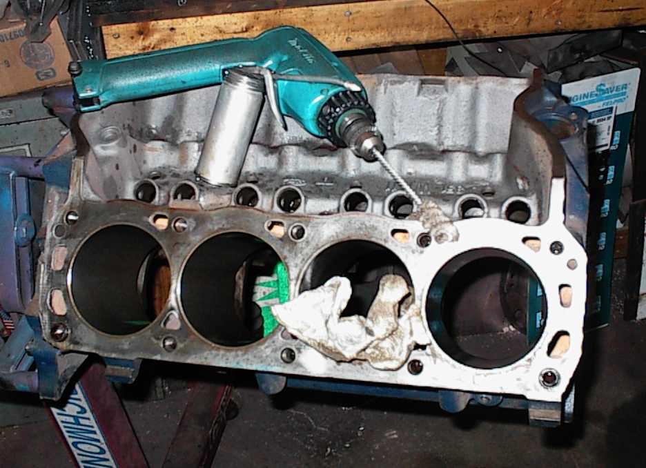
Abrasive brush cleans up the lifter bores and deburrs the edges of the oil
galleries.
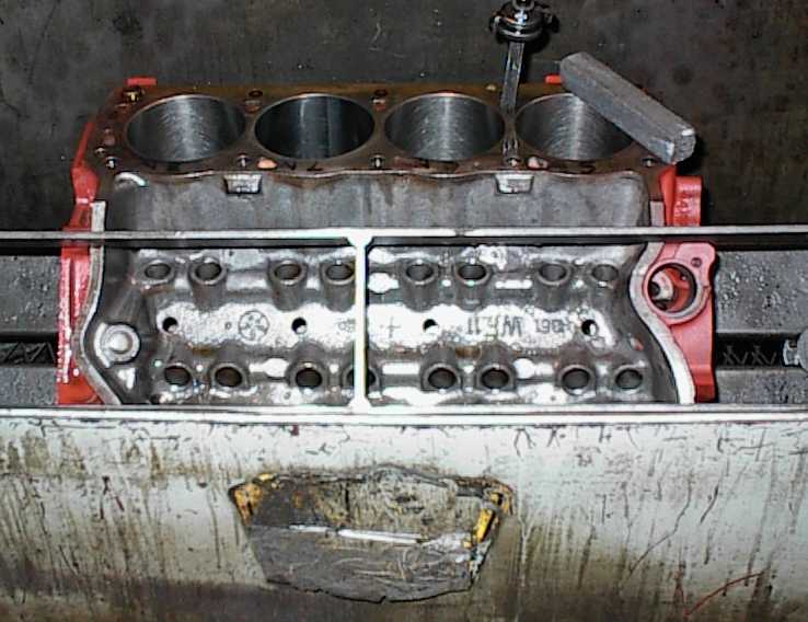
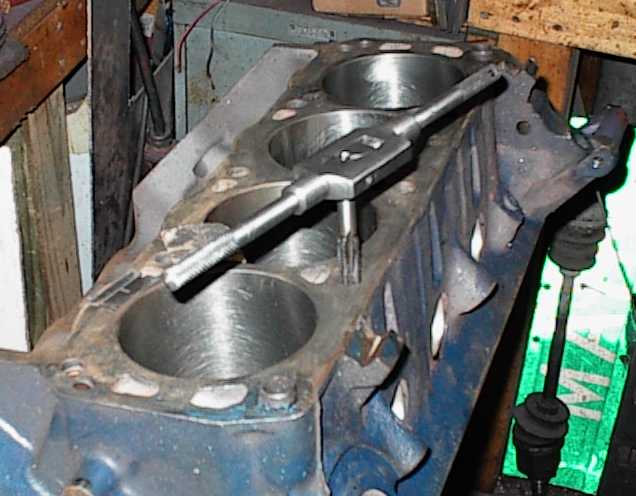
...and, of course, we tap the mains... #1 cylinder looks horrible here,
but it's just the usual brown crud that builds up as stuff sweats when the
temperature drops on humid days. Which is most of them, in Arkansas. It
wipes right off with an oily rag.

Doing the "oil mod" to pressure-feed the distributor gear. .125" hole most of
the way down to the distributor shaft oil passage, .060" through. Oil squirts
directly up onto the distributor gear. It ought to be helpful with the steel
cam.

The intent of my little flashlight was to light up the oil hole. Didn't seem
to do much, but you can see the hole.
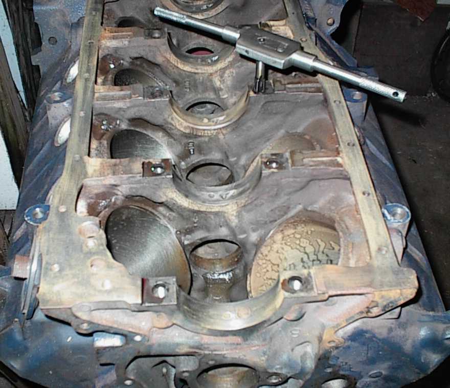
After kicking around for more than a decade the block needed a little TLC. I
cleaned up the machined surfaces with fine sandpaper.
Now we tap the holes so the head bolts will torque down cleanly...
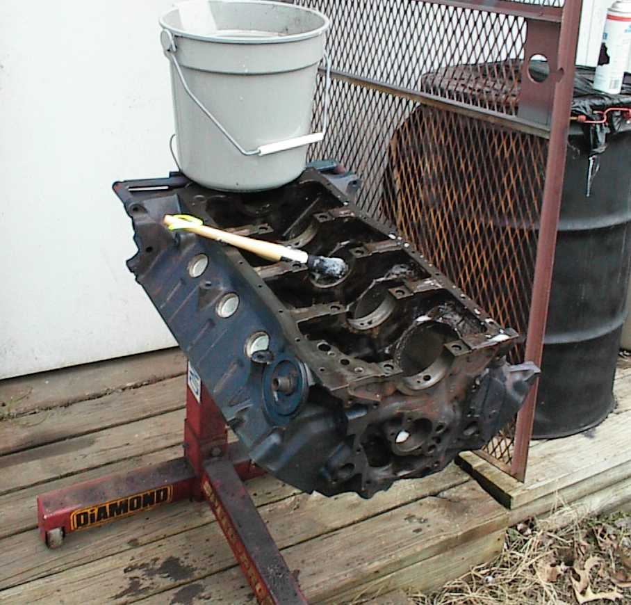
Cleaning up with a brush and laundry soap. Scrub-a-dub-dub... it was a bit
chilly that day.
Did I mention chilly? More like freakin' FROZEN...
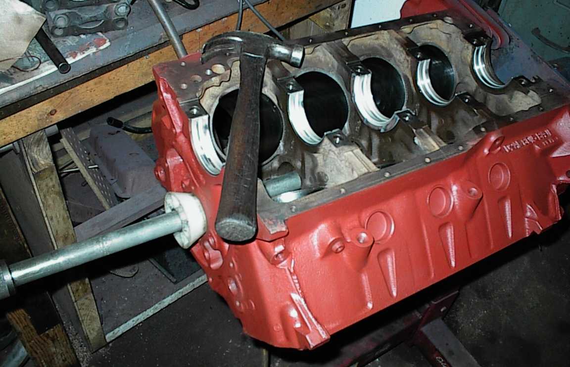
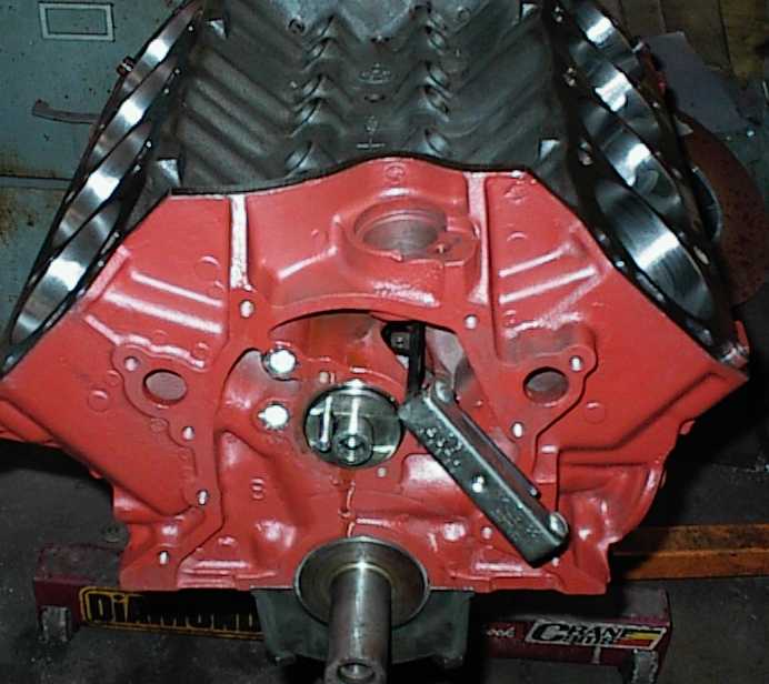
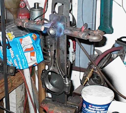
The old whacko-smacko to install the cam bearings. The crank has been in and
out a few times, checking stack height, valve/piston clearance, etc. The soft
indium overlay is wiped off in spots.
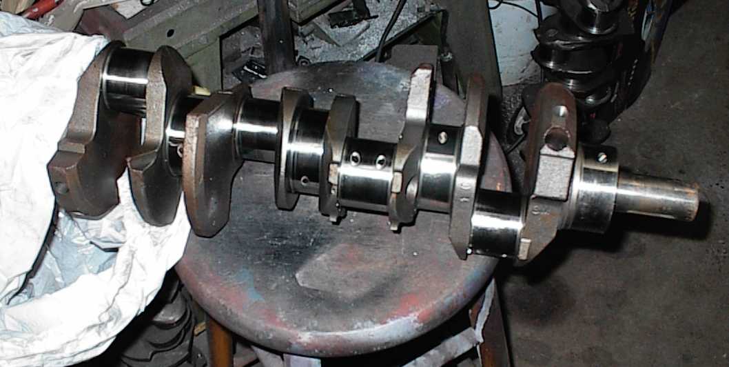
The crank had been stored in its packing box for twelve years. It needed some
polishing, as you can see here.
Checking the fit with Plastigage prior to final install. Inside and outside
mikes tell you the sizes, Plastigage helps tell you if the crank is bent or
the mains are out of alignment. Every tool has its purpose.
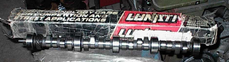
Used Lunati roller cam for 351W. I got it from a guy on the Fordnatics
mailing list. It should be lumpy but not unstreetable.
Installing the driver's side lifter gallery plug. A little Teflon pipe dope
lets it come out without drilling next time. The other two plugs are pressed
and staked into place.
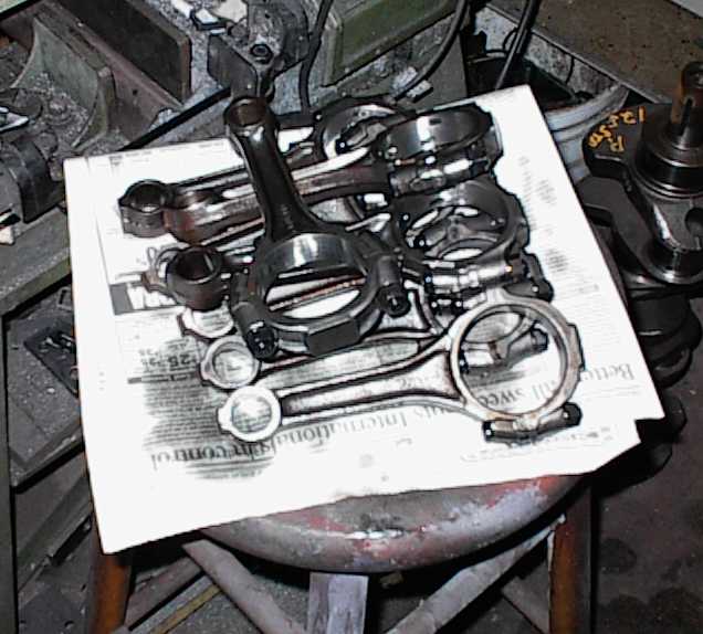
The connecting rods had gotten a bit rusty in storage, so they got wire-
wheeled and washed in solvent after being rebalanced and resized. The rods
were shot peened by Racing Head Service in Memphis. I installed ARP bolts
before I resized them.
Homemade rod heater fixture expands the pin end enough to slide the pin
through.

And the coated, cleaned pistons await being mated to their rods...
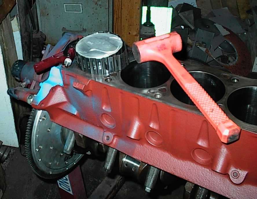
Pistons hung, rings gapped and installed, rod bearings installed, ready to
install.
...flip the block over to install and torque the cap.

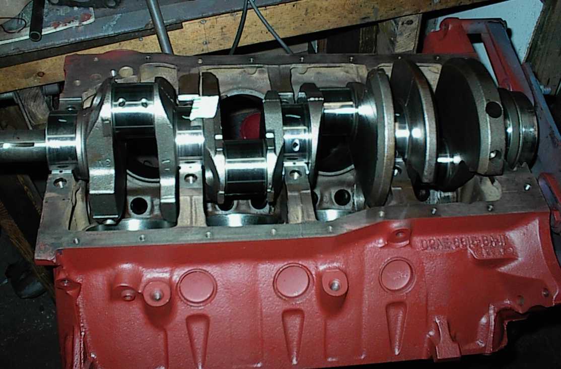
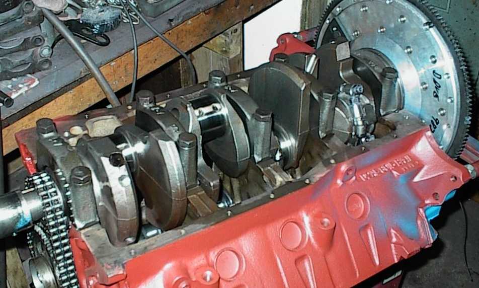
Assembled short block after degreeing the cam.

Finding the depth for the pan baffles. At 4.5 quarts, the depth is only 3"!

Here's a different angle.
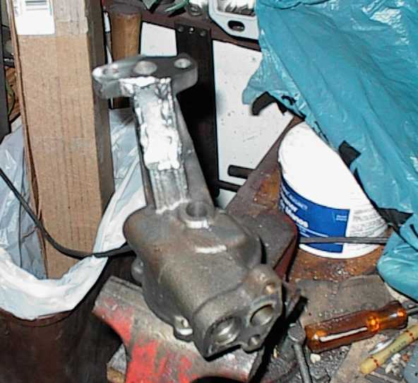
Melling high volume oil pump had been clearanced for a big stroker motor. I
went a little too far and hit oil. Oops. Here I've ground down to fresh
metal along the affected area.
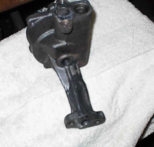
Here, I've welded a steel patch over the thin spot and hole, and spread epoxy
over the whole thing. Yeah, well, I wasn't going to throw a brand new pump
away, and Mark got it as a freebie.

Checking pushrod length.
The valve springs required a 1.88" inch installed height. No problem, just
toss the head on the seat/guide machine and cut .100" or so from the seats.
Unfortunately, five out of eight exhaust seats were paper-thin after that; I
only noticed because one hit water. I broke through the other four by poking
with a screwdriver.
This was the last step in prepping the heads - they had been set up for screw-
in studs and guide plates, milled, new guides installed, set up for Windsor
water flow, and the seats ground. AAAAARGH! I consulted with some other
local shops, who recommended throwing them away and starting over with a fresh
pair of heads.
But no, I'm stubborn... so I found a Chevy-size spring (1.25" diameter) that
would work in place of the 1.45" Ford spring, and was shorter too. That gave
me .125" to work with... all I needed were some spring seats of the proper
configuration.
Of course, nobody made any seats like that. So I decided to do it myself.
The seat pockets were 1.5", so I bought a chunk of cold-rolled 1018 steel bar
stock and lopped off nine pieces with the bandsaw.

Here I'm drilling holes through, just under the valve guide size. For some
reason I didn't take as many pictures of all this as I thought I did.

One finished seat, drilled, faced on both sides, and counterbored. Probably
75% of the metal has been removed. Yes, children, this is "billet," meaning
"whittled out of a chunk of metal."

Cups and cleaned head ready for work.

I used a long bolt and a piece of tubing to preload the seat into place.

...another shot.

Finished product. Yes, that's all done with the MIG welder. It took half an
hour to knock off all the spatter beads.
Mark wants to run EFI on the 351X, so I modified the intake to accept
injectors. Since 22# injectors are junkyardable at $5-ish each, as opposed to
$45-ish each for new 45# injectors, I put in sixteen injector bungs. Besides,
the "forest of injectors" look is way cool.

There was a giant vacuum bung that one injector went almost through; it had
to be ground off.

Wood strips and bolts hold injector bungs together.

The guy who welded the bungs in let them slip down into the manifold. He ran
some beads around the openings after he burned parts of the bungs away.
[sigh] It'll take a lot of work to clean this up.

Since he let them slip down, there's plenty of bung underneath. I'll have to
grind all this out.

...and here I am, grinding. And grinding. And grinding...