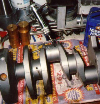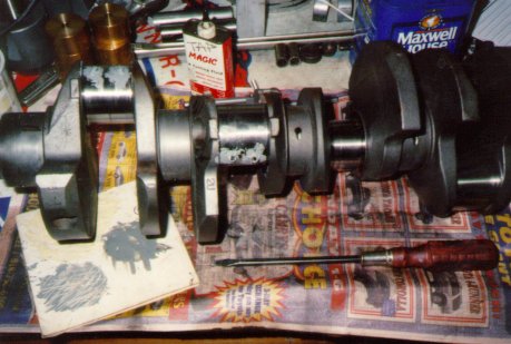
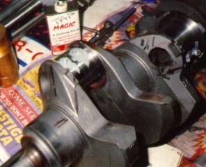
Various FE experts had assured me that a 390 crank could not be stroked to any useful degree, that the oil holes would walk off to the sides so far the crank would simply fountain oil onto the cylinder bores. Taking the lore at face value, I drilled, tapped, and plugged the oil holes with hollow plugs before grinding the rod throws. This would move the oil holes about .090" inboard of their original positions. As it turned out, either I got a freak crank of the 'experts' were full of it; the holes didn't walk any more than is common on, say, a 347 small block stroker.
The plugs are an interference fit, torqued solidly down, and epoxied in place. They're not going anywhere, though they're not accomplishing anything useful. The smaller diameter oil hole doesn't hurt a thing.
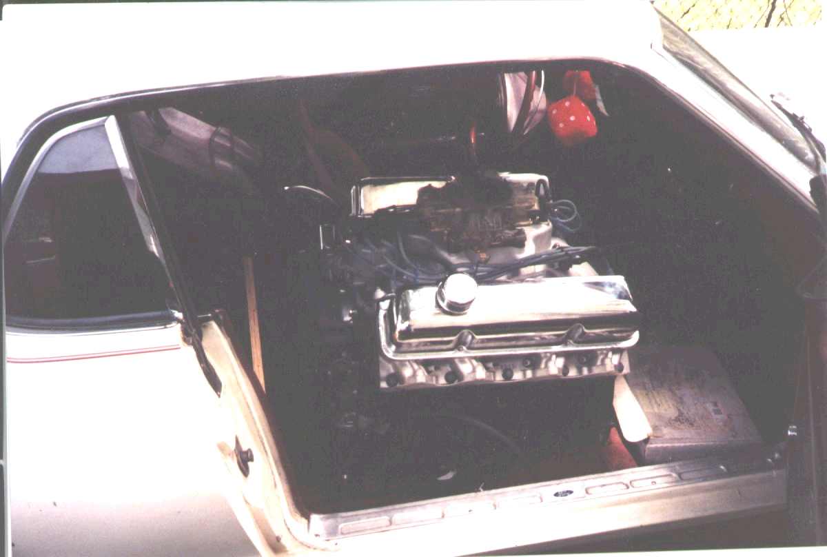
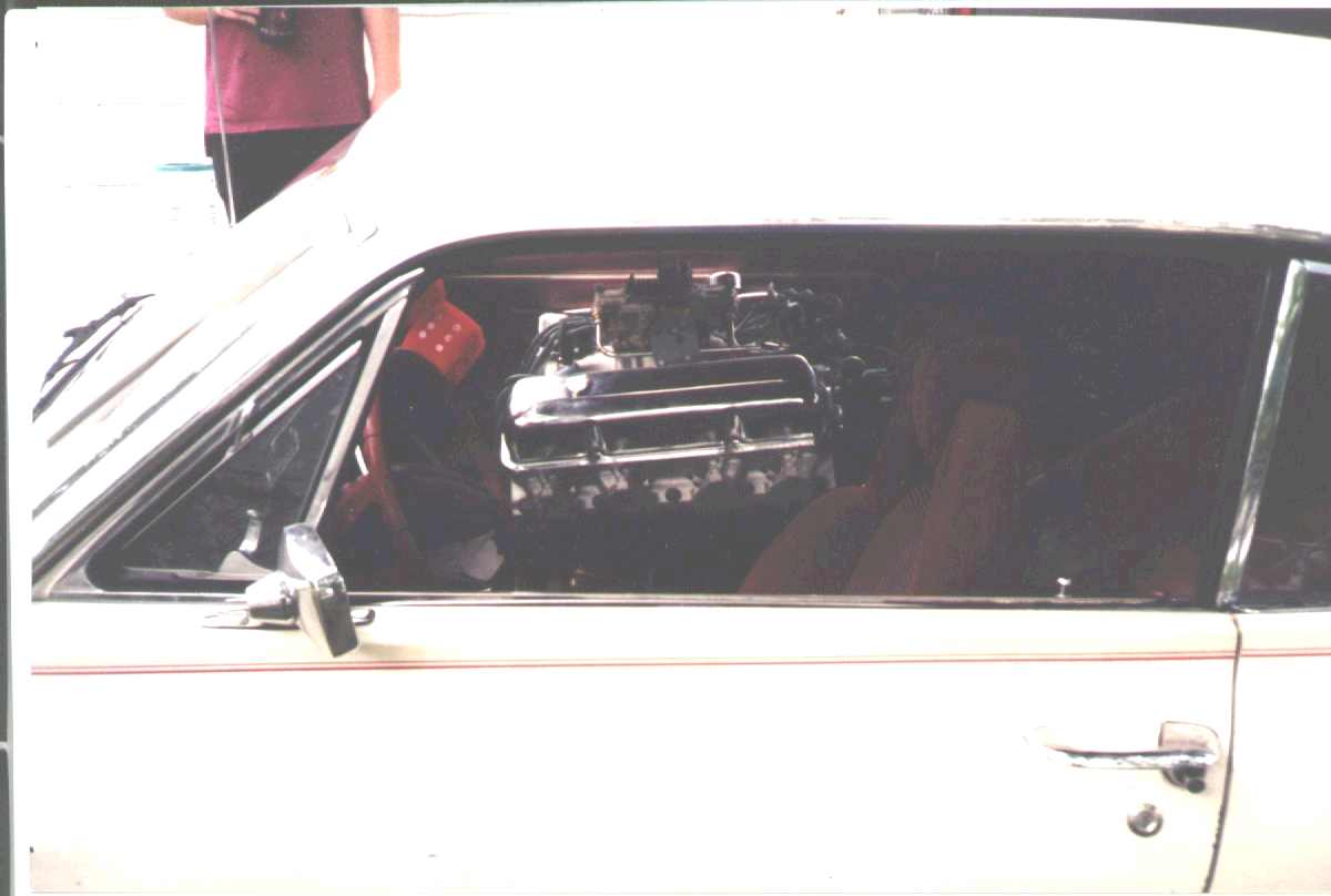
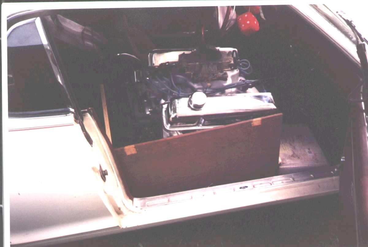 Sean was out relatively near my place after I got the engine done; well,
closer to my place than his, anyway. He dropped in and we loaded the 443 into
the passenger side of his '68 Cougar. Looks rather at home there, wot?
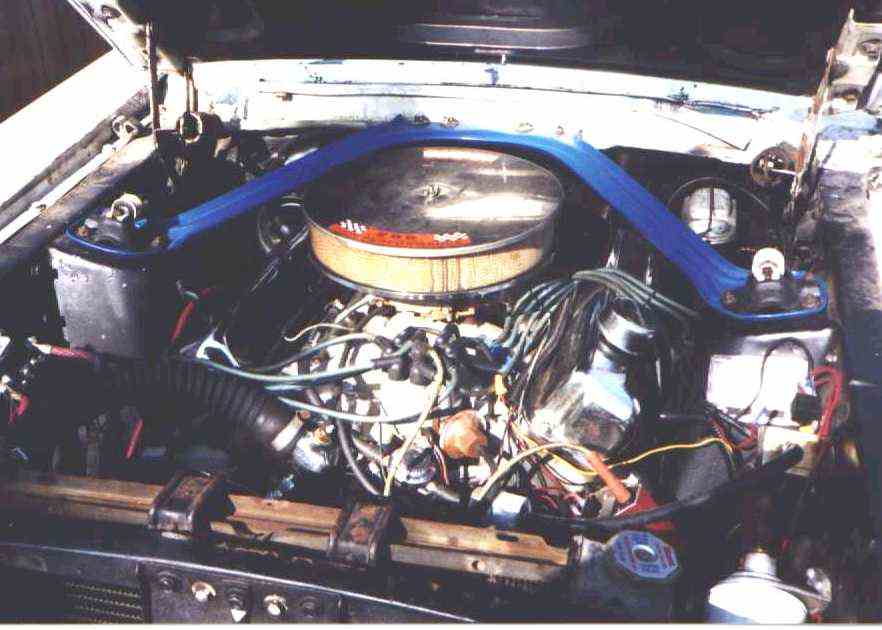 A shot of the 443 in the car. Notice the cool "289 High Performance" sticker
on the air filter lid. [grin] Hooker Super Comp headers have negative
engine compartment clearance.
Build Sheet:
===========================================================================

443 Ford FE stroker for Sean Korb, Raleigh NC


COMPONENTS ---------------------------------------------------------------

block:
        FT Ford - has large distributor shaft hole, oil drainback plug above
                  pan rail, triple-braced main webs
        bored to 4.185"
        #4 bore sleeved
        bores honed to #320 smooth finish
        new cam bearings (King)
        decks cleaned up on abrasive surfacer
        all threaded holes chased
        all oilway plug holes tapped 1/2-13, threaded steel plugs installed
        2 piece rear main seal (Ultra Blue silicone around edges)
        new core plugs (Ultra Blue silicone sealer)
        painted  (Rustoleum Satin Black)
        drilled oil pump to adapter passage out from 3/8" to 7/16", radiused
          with Dremel, chamfered opening
        brass bushing to adapt distributor hole from FT to FE size
        Hard Block filler halfway up water jacket
          depth from deck surface:  (measured through deck holes)
                left      right
                 3.6       3.6     front
                 2.8       2.9     middle top left
                 2.4       2.9     middle top right
                 2.7       2.6     middle bottom
                 2.4       2.9     rear

pistons:
        Federal Mogul (Badger) 400 SBC NP400 castings, .060 over
        .075 machined off top
        top ring land thickness: .155
        ceramic coated tops
        TLML moly coated sides
        fitted to .0015 clearance at bottom of skirt

rings:
        Speed Pro 400 SBC, .060 over, moly top ring
        4.155" Pontiac oil expanders  (slightly less tension than Speed Pros)
        file fit - top, second, oil all gapped to .018"

rods:
        225 Slant Six, 6.7", forged steel  (std FE rods 6.54")
        glass beaded
        big ends resized
        machined .164 each side   (1.205 stock width)
        new nominal rod width .874"
        ARP rod bolts (360 Chrysler V8)
        small ends sized for .0015-.0020 press fit with .927 (SBC) Chevy pins
        .070 tall by .040 deep chamfer on crank cheek side
        oil squirt holes point to camshaft
        side clearance:  .008-.011"
        bolts stretched to .0065" on assembly  (approx. 70 ft-lb)

===========================================================================

rod bearings:
        225 Slant Six, standard size  (TRW)
        one side machined .040, other .100
        rod bearings TLML moly coated
        rod bearing chamfered crank cheek side

crank:  390 Ford, cast
        stroked to 4.020", 2.187" Slant Six rod journal dia (std.)
        rod journal width 1.767 (std 390)
        mains turned .010
        oil holes plugged, redrilled
        lead-in grooves cut in mains
        polished journals

main bearings:
        .010 under  (King)
        360 degree oil groove
        TLML moly coated

heads:
        Edelbrock
        Perfect Circle type valve stem seals, all nylon
        adjustable rocker arms
        rockers refaced and internally honed
        rocker shafts:
          clearance .002-.0055  limit .006
          rocker ID .842-.844
           shaft OD .839-.840

===========================================================================

ignition:
        Ford Duraspark distributor
        distributor shaft bushing:
          brass     material
          .448      distributor shaft bottom diameter
          .900      bushing length
          .517-.518 bushing diameter
          .450      bushing ID
          .525      oil hole CL from top of bushing
          .25       oil hole diameter
          .015      internal and external chamfers

===========================================================================

balance:
        internal (390) balance - crank counterweights drilled

        468  rod rotating
        468  rod rotating
        50   one rod bearing
        50   one rod bearing
        748  one piston and pin
        63   one ring set
        196  rod reciprocating
        5    oil allowance
        ------
        2048 bobweight

        set up speed 800 RPM
        balance speed 650 RPM

        balanced front .5, rear .5
Sean finished up the short block himself - Edelbrock aluminum heads, Edelbrock hydraulic cam, Edelbrock Performer 390 intake, 780 Holley, a rebuilt electronic distributor and an MSD. The Performer 390 manifold is a real dog, with ports about half the size of the ones in the heads and much smaller than a stock 390-2V intake. Whenever he gets bored with the 443's performance he can always upgrade...
The 428 block I used had a small crack in the deck surface. I consulted with a couple of other local rebuilders, then asked Sean if he'd mind a crack repair on the block. He said no problem. I stop drilled, brazed, and resurfaced the block, but the fix didn't take. Torquing the heads apparently opened the crack back up enough to trickle water into #6 cylinder. Damn!
I located an FT (truck) block, prepped it, made a bushing to go in the distributor hole, set it up for screw-in oil plugs, and swapped the block after Sean pulled the engine out of the car. The 443 runs much better on all eight cylinders... sometimes these things happen.
The FT block is about 25 pounds heavier than the 428 block due to the extra metal. Even with that, the 443 is lighter than the 351 Cleveland he had in the car before. The FEs are nowhere near as heavy as the ragazines make out, at least when they're not wearing the stock 72-pound cast iron intake manifold...
Then there was trouble again! Sean said the oil pressure was fine when cold, but dropped off steadily as it warmed up. He dropped the pan and put a high pressure pump in, and tried synthetic oil, but neither helped much. After the engine reached full operating temperature the oil pressure would drop below 6 PSI, the hydraulic lifters would collapse, and it would quit.
So Sean yanked it back out, stuffed it back in the Cougar, and we transferred it to my truck in Tennessee. I got it back home and tore it back down.
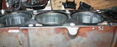 Uh-oh. It's been hot. Really hot! Sean said the temp gauge never went over
200, but we have a bunch of galled cylinders.
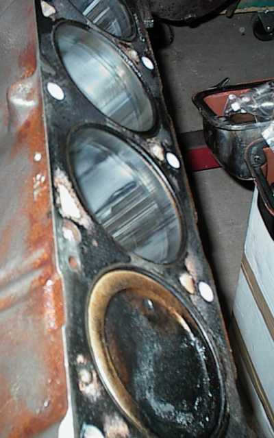 Galled on both sides, not just the thrust side. The pistons had picked up
iron from the bores, and there were wads of aluminum welded to the cylinder
walls.
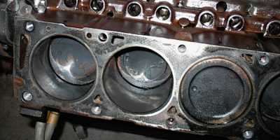 Flame patterns look okay, but there's way more oil on the pistons than there
should be.
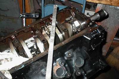 Now the pistons come out. The rod bearings were beaten down to copper, and
the mains weren't so good, either.
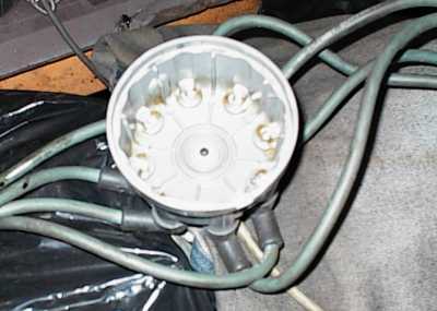 Here's another problem - carbon tracking and signs of crossfire in the
distributor cap.
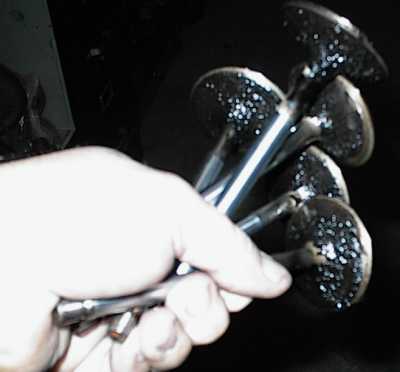 And here's yet another problem - oil running down the valve guides. I'd told
Sean the white nylon seals Edelbrock put on the heads were no good. He didn't
want to change them, so that's what the engine used; I just washed the heads
and bolted them back on the motor when I swapped blocks. Edelbrock no longer
uses those seals.
There's about a hundred miles on this build.
Diagnosis: detonation. Sean says he never heard any, but with those leaky, rattly Super Comp headers, who could tell? I've driven the car and I don't think I'd necessarily notice a borderline condition either.
Pinging puts a lot of heat into the cylinders. I'm pretty sure it was pinging: the CR was about 11.2:1, it was passing a bunch of oil past the valve seals, which tends to promote detonation, the tiny Edelbrock cam aggravated things by keeping the cylinder pressure high, and the crossfire from the bad distributor cap sure wasn't helping anything.
The plan: get rid of the detonation, help get rid of excess heat, and improve the oiling system.
 Sean's original FE had come from a full-size car and had the oil filter
adapter that stuck straight out the side. That wouldn't work in his Mustang,
so he went to an adapter and a remote oil filter. I figured there would be
some pressure loss in the hoses, and all the oil would drain back out if the
car sat very long, since the filter was higher than the adapter.
I had a Buick oil pump cover on hand. The cover has provision for the filter,
plus it has the regulator for the Buick oil pump. And it would all tuck
neatly alongside the 443.
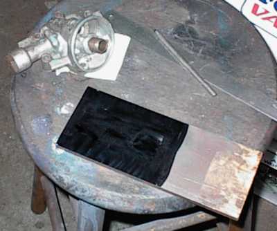
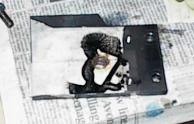 I've rough-cut the adapter out of 3/8" steel. The oil passages in the Buick
pump cover are weirdly shaped. I used the old "hit it with spray paint and
whack it onto some tape with a mallet" trick to transfer the shape of the
inlet passage to the adapter plate.
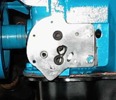 Fairly far along here - porting the adapter to the block, the bypass fitting
is installed, and holes are drilled and tapped to mount the cover. The big
hole is from the pump, the smaller one feeds the main oil gallery. The Buick
slot actually has more area than the Ford round hole, though it doesn't look
like it.
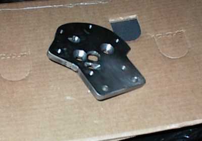 A little better shot of the feed slot here.
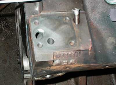 Here's what the block looked like at the beginning.
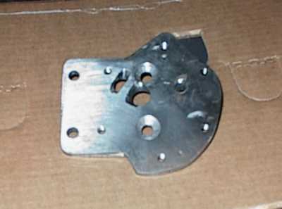 A gratuitous shot, because I spent a lot of time working on this thing.
Countersunk Allen bolts were necessary to clear the cover.
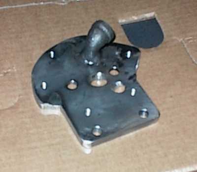 Simple street ell pipe fitting for the bypass.
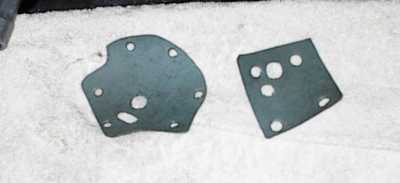 Making my own gaskets out of rubberized gasket material from NAPA...
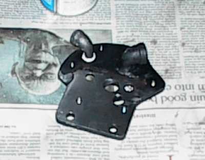 The small ell is for the oil pressure sender. The large ell is the bypass
line from the regulator.
It was sheer serendipity that the Buick cover tilted the right way, and that
the pressure and bypass ports hung off the front of the adapter pad on the
block.
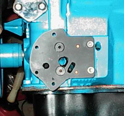 Done!
Done!
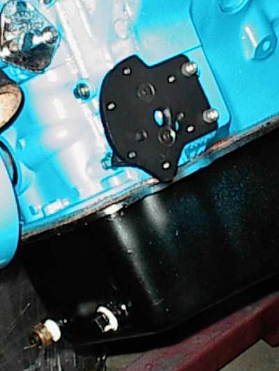 Finished installation. You can see the oil temp sender in the pan. The
bypass return port has a pipe plug.
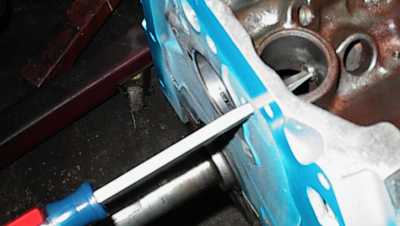 Inserting the new screw-in oil plug in the driver's side lifter gallery. A
little red Loctite holds it in place.
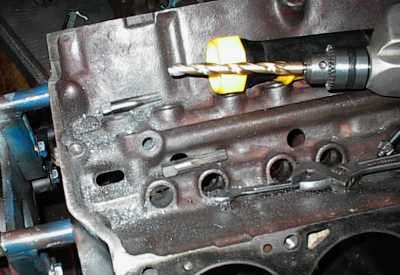 I removed the press-in oil plugs, then drilled and tapped for threaded plugs.
I made them out of 1/2" threaded rod with hacksawed screwdriver slots.
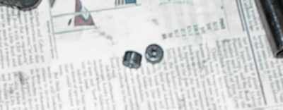 These restrictors have .125" holes and go into the lifter gallery passages.
Hydraulic lifters will work fine with .100" holes. I went a little bigger
just to be sure. The restrictors will keep more oil down in the rotating
assembly.
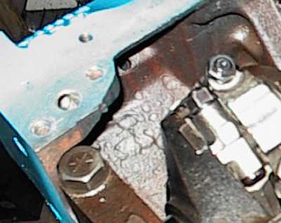 I had opened up the FT's oil passages some the first time around. This time,
I did a full port-match job to the new pump, radiused everything inside with
long oval cutters, and then polished it all. You can't see much here, though.
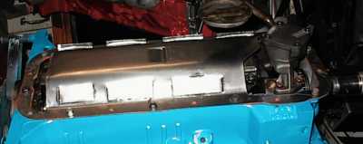
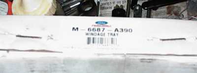 We added a windage tray. Good old M-6687-A390 was still listed at $35, but
Sean had to look fairly hard to find one. Apparently Ford's last production
run was some years back, and stocks are drying up.
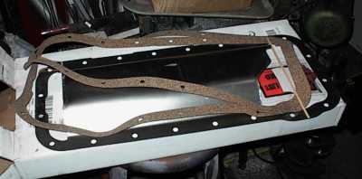 The box comes with the stamped-steel tray and two pan gaskets.
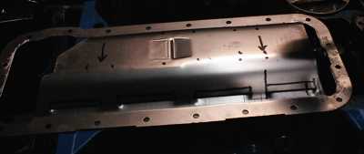 Naturally I wasn't going to leave the tray alone. First I figured out how the
oil flow would go, making notes with black felt tip.
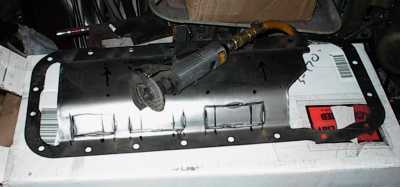 I figured the tray needed some windows so oil coming off the crank could be
slung out into the pan instead of bouncing off and riding back up into the
rotating assembly. The three windows line up with the connecting rod pairs.
The oil pump goes to the right, which is already cut out.
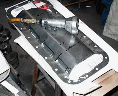 Air cutoff tool is loud, but fast. These tabs are bent the other way, to keep
air flow from slinging oil back up onto the crank.
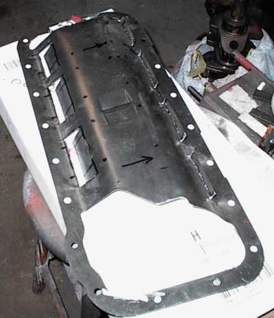 Here's a good shot. Air and oil get picked up by the folded-in tabs at the
left and dumped into the pan. More oil can get thrown out the parts to the
right, and the folded-out tabs keep oil from blowing back up.
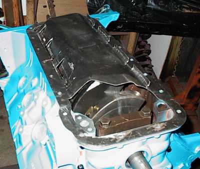 I had to fiddle with the left-hand tabs to clear the connecting rods.
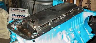 And here we are, done.
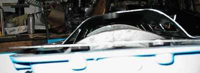 It's too dark to see the rods in there, but even with the stroker crank
there's room for everything to swing.
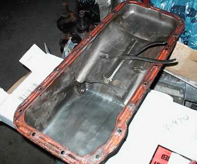
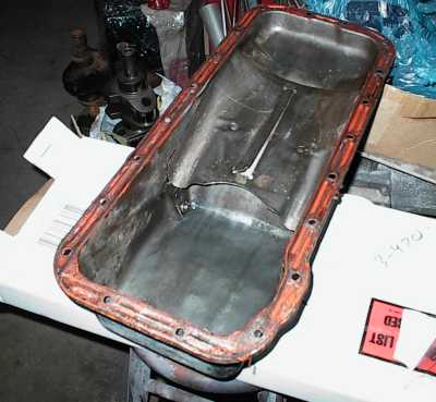 Sean's original 390 had this pan; baffle, scraper, and drain gutters. Some
pans had nothing, but this one's pretty good as far as stock pans go.
 I checked the clearance to the tray, and there was plenty. So I used some
duckbill pliers to bend the lip up. Anything oil exiting the ports I cut in
the tray should get caught by the lip and dumped back into the sump. That's
the theory, anyway.
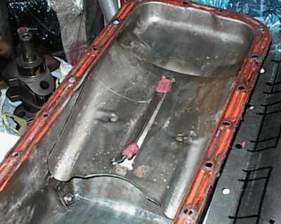 Modeling clay shows about 1/8" to the bottom of the windage tray.
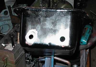 The external oil pressure regulator had to have some place to dump the bypass
oil back in the pan. I cut two holes in the pan, one for an oil temp sender,
one for the bypass return. Sean can run the bypass oil through a cooler if he
wants, at low pressure, without affecting the oil pressure inside the engine.
I figured returning the oil below the running oil level would reduce aeration.
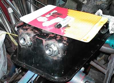 I MIG welded the bungs on, and though they checked out water tight, I epoxied
around them anyway. "Oil wants to be free."
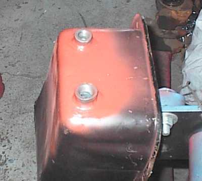 ...and the finished pan mod.
Pistons
Since the piston tops were machined down to adjust the pin height, and they're pressed onto the rods, I decided to sandblast the skirts and re-coat them. Yes, they were galled; I filed and sanded the iron pick-up from them before sandblasting. I've done several low-budget repairs on galled pistons with the belt sander and never had a problem.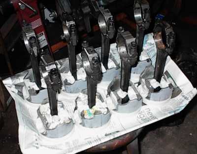 First we tape up everything so sand can't get in, then we sandblast.
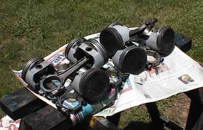 Detaped and washed.
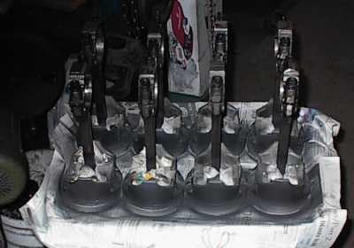 Recoating the pistons now. The tops were ceramic coated, and I left them
alone, other than wiping at them with a rag and solvent. No use to clean the
carbon off; it'll come right back as soon as the engine runs a few minutes
anyway.
 443 assembly on the right; the one on the left is from a Taurus SHO V6, if I
remember right.
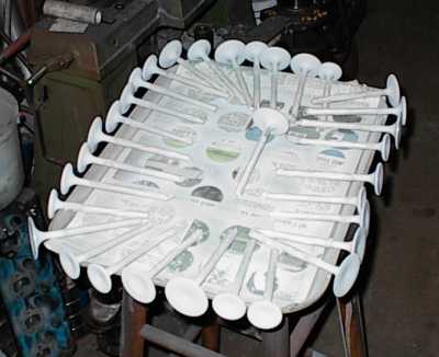 Since I'm trying to control heat, I sandblasted and ceramic coated the valves,
both the faces and backsides. They have to be re-ground after they're baked.
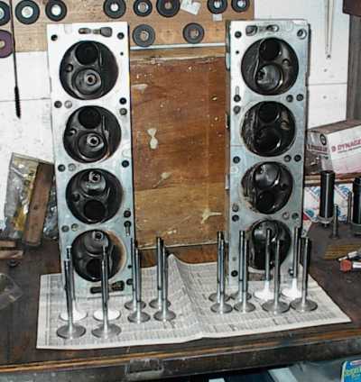 Ready to assemble. Again, I didn't worry about the carbon buildup in the
heads; I just hit them with Gunk and the pressure washer. This isn't a
rebuild, you know, it's just a repair.
The four white valves have an extra overlay of a different thermal barrier,
and go in the center holes. It's an experiment. Hey, I need to get
something for all this work...
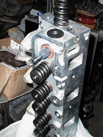 Reassembling the heads. Plain old 390 Ford rubber umbrella seals cleared
everything fine, with .030" clearance to the retainer at maximum lift. Note
the spring shims; the installed heights were all over the place from
Edelbrock.
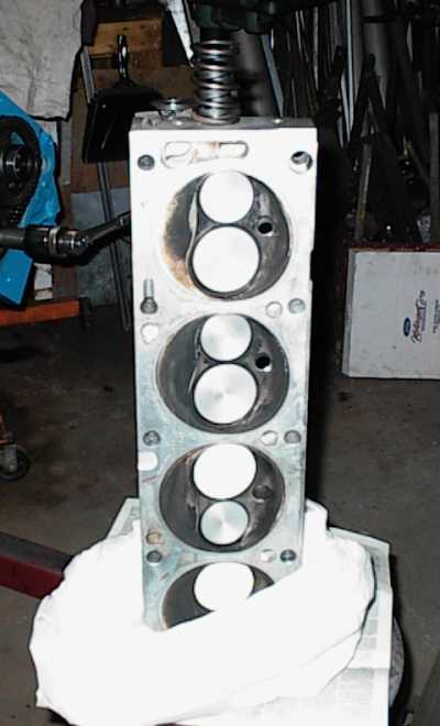 All done!
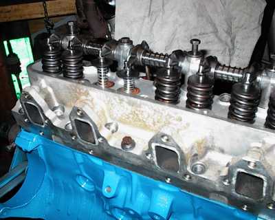 I'd sold Sean a short block, and then I'd swapped all his parts over to the
new block when the first one failed. Now I'm checking everything, just in
case. Light springs make things easier.
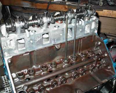 Why, yes, you can see the intake valves right there in the port openings...
with the solid checking lifters, the pushrod length, valve/piston clearance,
and rocker wipe patterns were okay. I did wind up having to shim some of the
rockers sideways since Edelbrock chose to alter the valve centerlines.
Sean had bought the cam and lifters as a kit from Edelbrock. He installed them after getting the 443 short block. I moved the parts over to the FT block, but as I said, all I was doing was replacing the block. The engine ran fine at the time. The guy Sean sold the cam and lifters to couldn't get his engine (a stock 390) to idle. After considerable diagnostics, he found out that Edelbrock had supplied the wrong lifters. Ford has two lifters - FE, and everything else, including six cylinders. The "other" lifters are longer, and a bunch of the valves weren't quite closing. The 390 ran, but it never ran quite right, and it wouldn't idle. I don't think that was part of Sean's overheating problem, and it would have been hard to tell given the commotion from the Hooker headers, but the valvetrain probably wasn't right in the 443. The FE valvetrain is non-adjustable, and Sean probably used the "spin the pushrod" test to check for clearance, as is recommended in many service manuals. Unfortunately, you can have the valve open a fair amount before you can't spin the pushrod any more. It's just not a very good way to check for clearance. Following the directions is good, unless they're wrong...
To reduce cylinder pressure at low speeds we went to a considerably larger
hydraulic cam. Lunati provided the correct lifters with their kit.
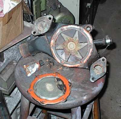 I took the water pump apart. It was a new pump when Sean put the engine in,
but I wanted to make sure the impeller wasn't spinning on the shaft, that it
had the right impeller, or the blades had somehow rusted off... everything
looked fine, so I put it back together.
...and now it's time to put it back together...
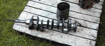 I ran the crank through the hot tank.
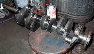 Now it gets hand-polished with a strip of emery, rodded out with long pipe
cleaners, and hosed with carb cleaner. It miked out fine.
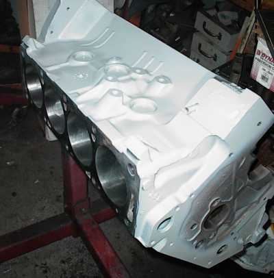 Some gray primer...
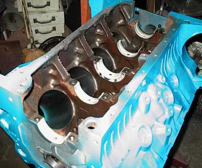 New main bearing shells. The oil holes in the block have been ground to match
the holes in the bearings.
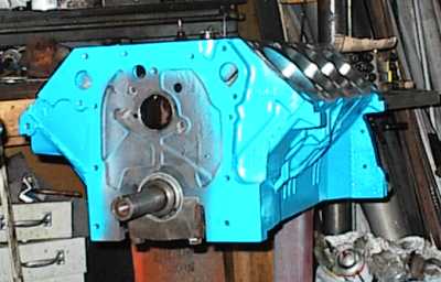 And here we have the crank and new cam bearings in place. A little overspray
gets wiped off with acetone.
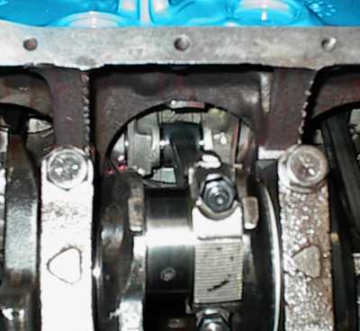 Just a gratuitous under-piston shot. Some engines don't have the rods
centered under the piston. This one does.
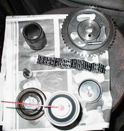 Cleaning up the timing bits before reinstallation.
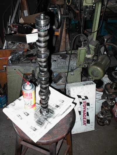 Sean sold the weenie Performer cam to a buddy and bought a righteous Lunati
stick much more suitable to the engine's configuration. I'm cleaning the
shipping goo off here; it picks up lint and stuff that you need to get off
before you apply cam lube to the lobes.
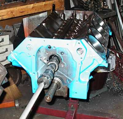 After applying moly cam grease to the lobes we slide it in with the cam tool.
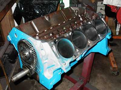 Cam in, drive paraphernalia installed. Blue Loctite on the retainer plate and
sprocket bolt.
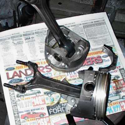 Re-coated, cleaned, big ends resized, and ready to install. If you look at
the side of the big end in the middle you'll see a silver spot. That's a 1/4"
x 1/8" slot I ground into the crank-cheek side of the rod shank. This directs
the oil exit path up to the underside of the piston instead of just oozing out
everywhere. Many late-model Japanese engines do this. It's not a cure-all,
but if the oil is going to exit anyway, it might as well help lube the
cylinder wall and cool the underside of the piston, right?
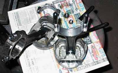 These are late-model Slant Six rod bearings, which are narrower than the early
ones that I used the first time around. I had to narrow those on the lathe.
These drop right in. You can't quite make out the oil slot in this picture,
for some reason. Digital cameras can be weird.
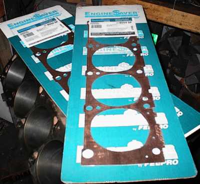 .020" thick soft copper head shims. These are made for blocks that have been
decked. I had machined the pistons for zero deck with the 428 block, but the
FT block had been severely decked, and some pistons were sticking out .015".
The pistons maybe weren't quite touching the heads, but the quench
areas were bright and shiny. These will take care of that, and lower the CR a
bit without hosing the quench. Every little bit helps.
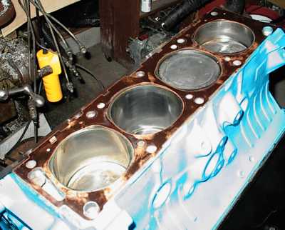 Checking the bore clearance around the shims. Close, but okay. FE head
gaskets have irregularly-shaped holes that don't match the round cylinders, so
I'm making sure the shims don't zig where the gaskets zag.
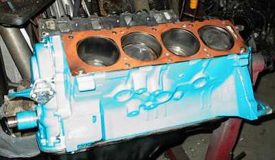 I hosed the shims with KW Copper-Kote spray sealer before assembly. I figured
the block deck was the most rigid surface, to I put them against the block and
laid the head gaskets on top. There weren't any directions with them, so I
figured Fel-Pro didn't care.
Later I bought some shims for a different engine, and Fel-Pro has included an
instruction sheet with them saying to put them on the block side. Good.
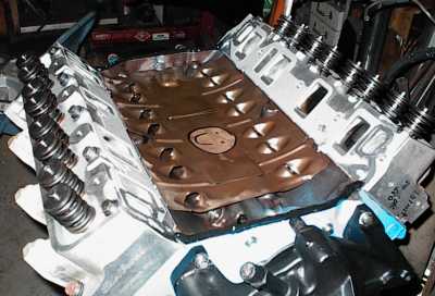 The original lifter tray from the 390. I drew the happy face on it with a
felt tip, just for grins. I'd also sprayed some WD-40 on it because it kept
trying to rust. The WD-40 migrated to the edge of the ink, but wouldn't
cross. Useless to know, but what the heck...
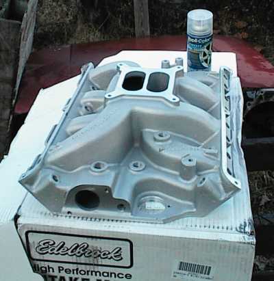 Sean also sold the weenie "Performer 390" intake, which had ports smaller than
a 5.0 intake, and bought a "Performer RPM" manifold that looks considerably
better. I shot it with high temp wheel paint that's not supposed to turn
yellow.
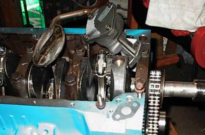 New high volume oil pump. I checked the pickup to pan clearance with clay.
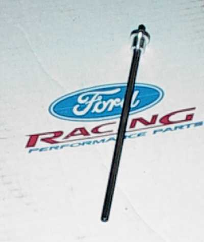 I put a brand new Melling oil pump shaft in. It had a cheesy circlip that was
supposed to keep it from falling out of the pump when you removed the
distributor. I made an aluminum collar on the lathe and pressed it on. I've
seen those little clips break. My collar isn't going anywhere.
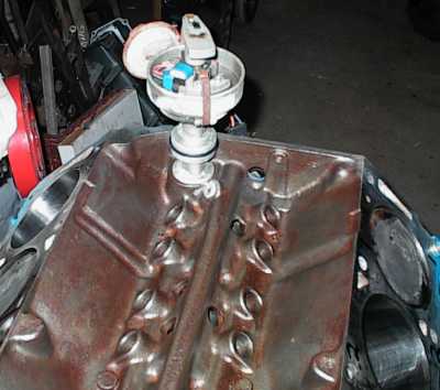 This is how an FE distributor sits in the block. The V-shaped gasket seals it
where it passes through the intake manifold. The hole in the intake is plenty
big! Note epoxied-over screw-in oil plug.
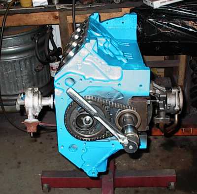 I installed the oil pump and distributor, then wiggled the drive rod back and
forth to make sure it had plenty of engagement at each end. I'd seen them
partially strip a distributor before, causing low oil pressure. Then I
pressed the aluminum retainer along the shaft so the rod couldn't come out of
the oil pump.
It was easiest to do all this with the engine flipped onto its side.
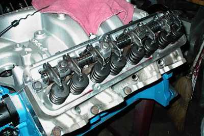 Heads and intake on, rocker shafts in place.
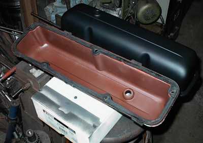 The Taiwan-chrome valve covers and thermostate neck were rusted and pitted. I
cleaned them up, hit them with Rust-Oleum red primer, and painted them flat
black, mostly because I had several cans on hand. Sean can repaint them later
if he wants.
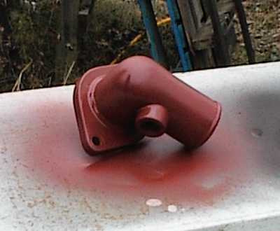 The cheap aftermarker chrome water neck wasn't looking so hot either. It
got primed and painted too.
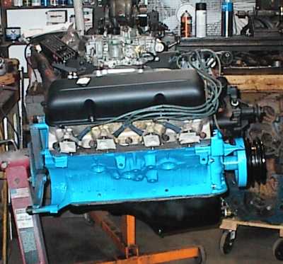 Passenger side of finished engine.
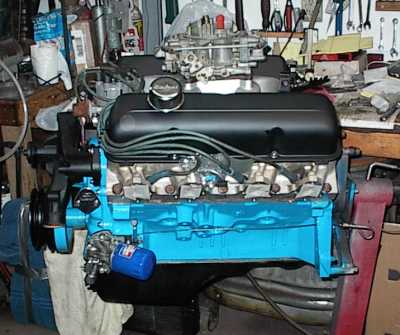 Driver's side, with new external oil pressure regulator and filter adapter.
The new dipstick tube is in place, but I haven't trimmed the stick yet. The
pistons are Chevrolet, the rods are Chrysler, the regulator is Buick, and the
dipstick is from a Cadillac. "Parts is parts."
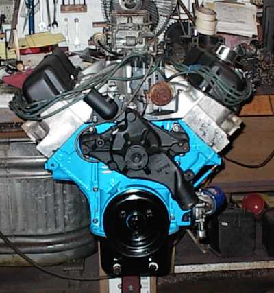 That was a new distributor 100-odd miles ago. It's humid in North Carolina,
too. The Buick adapter tucks in just as close as the Ford one and should
clear everything in the Mustang's engine compartment.
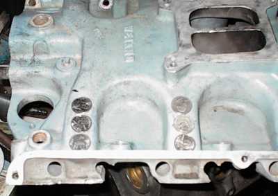 Sean sent along an antique Weiand single-plane intake that he wanted injector
bungs installed into. Here, I'm using quarters to show that there is room for
24 injectors, should he care to go that route. He'll probably wuss out,
though.
And now it's into the Malibu and off to Kenney's, to go into his '51 Ford pickup. This time we're going to run the snot out of it before it goes back to Sean, to make damned sure.
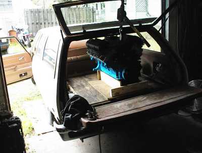 I made the wooden carrier just for this trip; the pan touches the half-inch
plywood base, and there's a finger's width of space at the roof when sliding
the engine in.
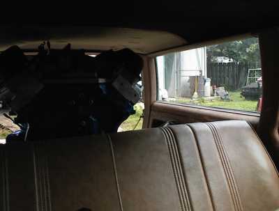 Once it's inside there's more room. A Malibu wagon is an intermediate sized
car, but the 443 looks enormous.
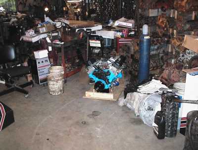 Sitting in Kenney's shop, waiting for installation into his '51 Ford.
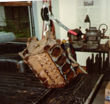 Here's the 428 block. Finding the block was the only difficult part of the
whole build.
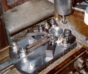 Narrowing one of the Slant 6 rods. I used to clamp the rods to the table and
hope they stayed put. Since so much had to come off the Chrysler rods I
finally broke down and built a proper fixture to hold the rods down properly.
Center spuds can be changed out to suit different rods. You can see an
aluminum disc under the spud to hold the rod up off the fixture; many rods
are wider at the small end than the big end. Shims under the small end help
keep the rod flat when the clamps are tightened.
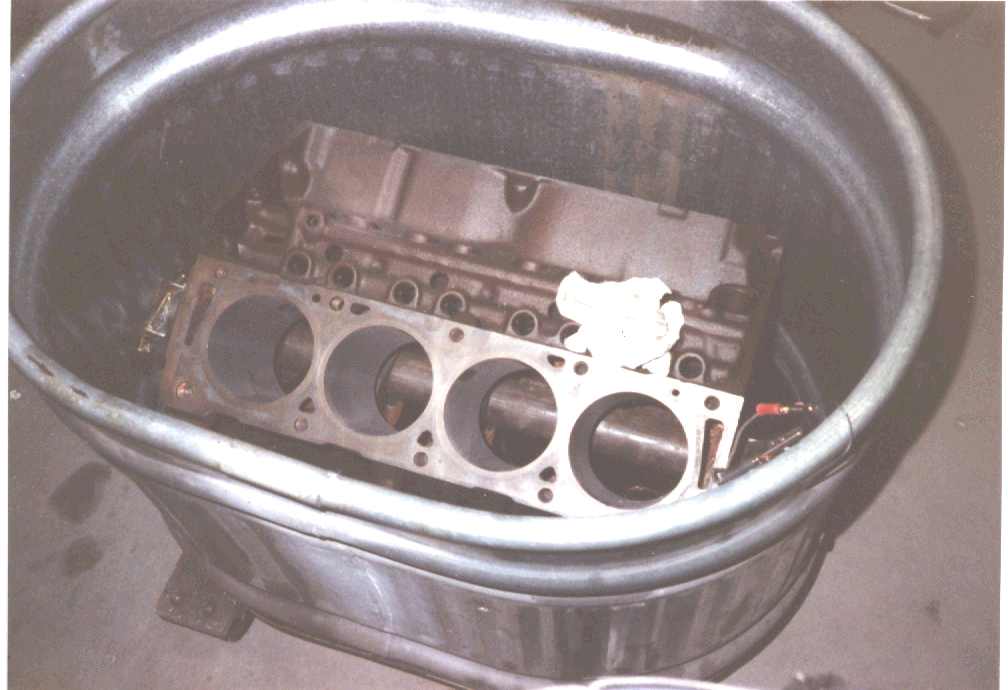 Honing the block. I had to beat a divot into the side of the tank to clear
the FE's bellhousing flange, which is quite wide. High volume pump and hose
flood the cylinders while honing. They make special honing oils, but I've
found that #2 Diesel fuel works just fine.
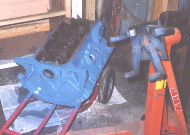 Here's the cleaned, bored, honed, and painted block. The next step is to put
it on the engine stand for assembly.
