Author: Dave Williams; dlwilliams=aristotle=net
He wanted an old Ford 226-cubic-inch 1951 Ford flathead six. Modify the intake and exhaust manifolds appropriately, then add the '148 SEFI DIS engine management system from a Buick Grand National, along with its turbocharger. The GN engine is practically the same size and the '148 is thoroughly cracked, so changing the fuel and spark curves shouldn't be a big deal.
Put it in, oh, a 1972 Mustang, because it's there. And make an adapter plate for an AOD while you're at it.
Because it's a Bob project, he wanted to mount a Diesel pump and injectors for direct cylinder injection, and he wanted to run both the Buick DIS and the distributor, each firing six plugs. And some other stuff, but I'm not going to say anything until I have pictures...
Flathead sixes don't grow on trees, but I had found the engine for Bob in fall of 2002. Shortly after Christmas I went to get it, a place an hour away. I pulled into a convenience store a couple of miles off the freeway on the other side of Little Rock in a light drizzling rain to get a Coke and a cherry pie for breakfast. I opened Thunder's door, got out, and confronted Bob, who was standing in the freezing rain. It was a very Rod Serling moment; Bob was supposed to be in the wilds of Texas, many hours away. He was on his way to Little Rock with his mom, who had to see a medical specialist. So, by whatever twist of synchronicity, we both pull into a convenience store somewhere between East Jesus and BFE within seconds of each other.
[cosby] Right! [/cosby]
I picked the engine up and met up with Bob the next day. We fired up the heater and the air tools and set to work.
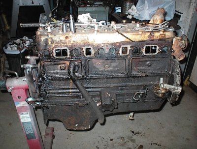
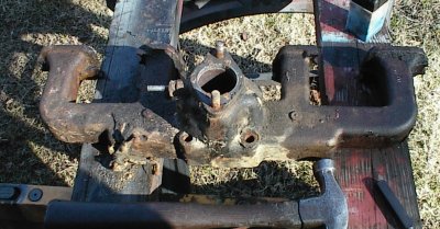
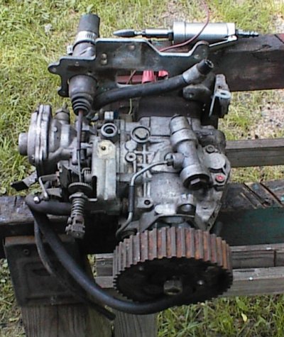
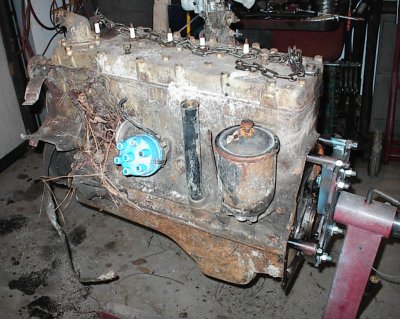 After unloading from Thunder and on the stand, left side. The engine had been
running when it was pulled from a '51 Ford, but it had been left outside in
the weather. Fortunately, it had been angled so no water got inside, just
condensation.
After unloading from Thunder and on the stand, left side. The engine had been
running when it was pulled from a '51 Ford, but it had been left outside in
the weather. Fortunately, it had been angled so no water got inside, just
condensation.
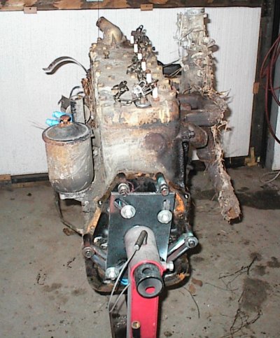 View from the back. The six uses a thick steel plate that bolts to the back
of the block. The bellhousing bolts to that, instead of cast flanges on the
block. The adapter plate and flywheel were pulled before we put it on the
stand.
View from the back. The six uses a thick steel plate that bolts to the back
of the block. The bellhousing bolts to that, instead of cast flanges on the
block. The adapter plate and flywheel were pulled before we put it on the
stand.
 Right side. Kenney had dragged it off into the woods to get it out of its
way; therefore the pine needles.
Right side. Kenney had dragged it off into the woods to get it out of its
way; therefore the pine needles.
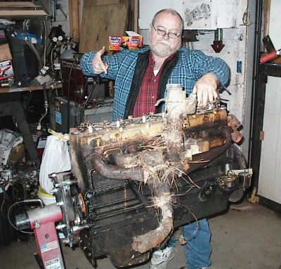
Bob is demonstrating his proposed horsepower injection technique.
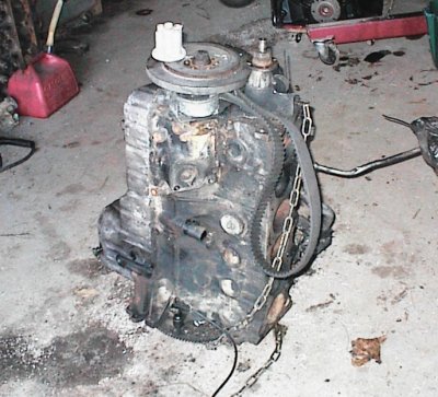
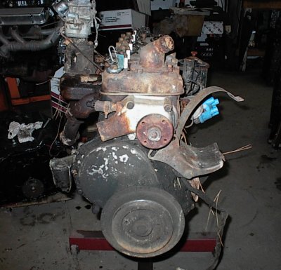 And finally, a view from the front.
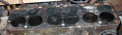
 Disassembly under way. Note that although the intake manifold is
siamesed, the block is not - this is a true twelve port engine.
Disassembly under way. Note that although the intake manifold is
siamesed, the block is not - this is a true twelve port engine.
The six was rated within a few horses of the V8 during its entire production
run, even though it had less displacement. There were a number of reasons for
that. First, the intake and exhaust porting were much better than the
V8, with bigger valves, too. The six also had a true Ricardo cylinder head
and flat-top pistons instead of the V8's odd domed arrangement, which was
apparently designed to avoid paying royalties on the Ricardo patents.
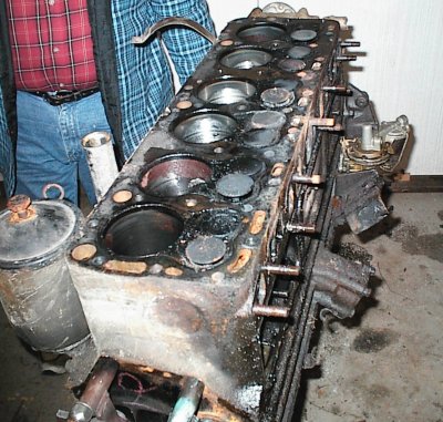 The engine wouldn't turn over, but when we took the head off the bores looked
fine. We used penetrating oil and kerosene to loosen things up, then started
tapping with a chunk of wood and a BFH. After a while we got it freed up.
The bores were fine. A couple of valves were stuck open, so we hosed those
down with penetrant too.
The engine wouldn't turn over, but when we took the head off the bores looked
fine. We used penetrating oil and kerosene to loosen things up, then started
tapping with a chunk of wood and a BFH. After a while we got it freed up.
The bores were fine. A couple of valves were stuck open, so we hosed those
down with penetrant too.
 So, after dropping the flathead off in my shop, we went junkyarding to look
for Diesel pumps. We struck gold on the first stop.
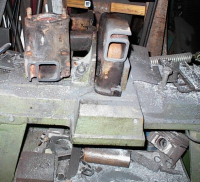
This is a BMW Diesel six from an early '80s Lincoln Continental. We snagged
it at the core yard due to one primary feature - it had a belt-driven
injection pump. We snagged the pump and crank sprocket for the flathead
before this shot was taken.
So, after dropping the flathead off in my shop, we went junkyarding to look
for Diesel pumps. We struck gold on the first stop.
This is a BMW Diesel six from an early '80s Lincoln Continental. We snagged
it at the core yard due to one primary feature - it had a belt-driven
injection pump. We snagged the pump and crank sprocket for the flathead
before this shot was taken.
The Ricardo's advantage is its resistance to detonation. It was designed to run fuel in the 65 to 70 octane range, not much better than Diesel fuel. In fact, one of these engines will run on Diesel fuel, as long as you start and warm it up on gasoline or naptha first. So it should be very happy on 89 octane pump gas and lots of boost.
The '148 engine management system will admit fuel in the conventional fashion, through ordinary Bendix-type solenoid injectors in the intake manifold. About 80% of the fuel - gasoline - will come from there. The other 20% or so will come through the direct injectors mounted in the cylinder head. Those injectors will be squirting #2 Diesel. To start with, anyway. Later they'll be squirting "gasocrap", as Bob experiments with recycled and bio fuels. Yes, adjusting all this on the fly is nontrivial. Bob did real-time programming for the Navy's missile program, he knows what he's getting into. The plan is to adjust the ratio of heavy fuel to gasoline on-the-fly, to just before the knock limit, or 100%, whichever comes first. Eventually, he figures to run straight heavy fuel at light throttle cruise, such as freeway operation. When he puts his foot into it and boost comes up, the ratio will swing the other way. Ought to be pretty trick.
The nice thing is, he can play around with the direct injection, then save his work, pop the baseline chip back into the '148, and drive off until he wants to tweak things some more.
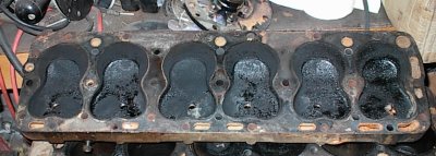 Here are the Ricardo-type combustion chambers. These are actually a slight
variant, using a C-shaped squish instead of a D-shape.
Here are the Ricardo-type combustion chambers. These are actually a slight
variant, using a C-shaped squish instead of a D-shape.
 Ordinary flathead valve arrangement, six bolts per cylinder.
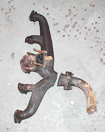 The exhaust manifold had a hot date with Mr. Bandsaw. It's not great, but
it's better than a lot of six cylinder exhaust manifold layouts.
The exhaust manifold had a hot date with Mr. Bandsaw. It's not great, but
it's better than a lot of six cylinder exhaust manifold layouts.
 The turbo flange will be welded on here. We were lucky that the hole in the
manifold more or less matches the turbine inlet; it saves a little work.
The turbo flange will be welded on here. We were lucky that the hole in the
manifold more or less matches the turbine inlet; it saves a little work.
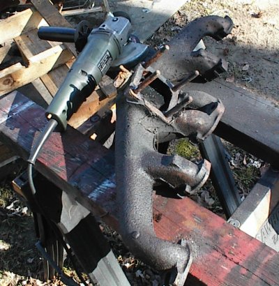 Now some work with the angle grinder to remove the large boss that connected
the intake and exhaust manifolds. We need the space for the new intake
plenum.
Now some work with the angle grinder to remove the large boss that connected
the intake and exhaust manifolds. We need the space for the new intake
plenum.
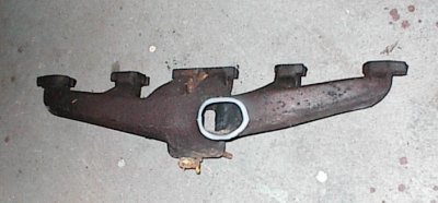
 Here's the stock intake. Simple iron casting, separate inners, siamesed
outers.
Here's the stock intake. Simple iron casting, separate inners, siamesed
outers.
 And the intake manifolds meets Mr. Bandsaw in its turn. I wound up with four
intake stubs about three inches long. Originally I had planned to do a six-
runner intake, but after looking at the way Ford did things, I decided to go
the way Ford did and siamese the two outers. The intake and exhaust flanges
interlock, with bolts and washers holding them to the block, and it would take
a lot of work to cut new flanges. And the way Ford positioned the bolts, the
outer runners needed to pinch in for access to the bolt heads anyway. This is
another case of "perfect is the enemy of good enough"; the paired outer
cylinders do not overlap their intake events, so it really shouldn't matter
either way.
And the intake manifolds meets Mr. Bandsaw in its turn. I wound up with four
intake stubs about three inches long. Originally I had planned to do a six-
runner intake, but after looking at the way Ford did things, I decided to go
the way Ford did and siamese the two outers. The intake and exhaust flanges
interlock, with bolts and washers holding them to the block, and it would take
a lot of work to cut new flanges. And the way Ford positioned the bolts, the
outer runners needed to pinch in for access to the bolt heads anyway. This is
another case of "perfect is the enemy of good enough"; the paired outer
cylinders do not overlap their intake events, so it really shouldn't matter
either way.
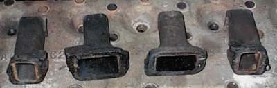 Here are the intake manifold stubs...
 The engine has been flipped over on its left side, slightly below horizontal.
The Buick turbo is positioned to see if it will fit. It just barely clears
the external oil pump, but it will work. The exhaust elbow points in wrong
direction; it would have to be replaced and an external wastegate plumbed -
except Bob has decided not to use the GN turbo now.
The engine has been flipped over on its left side, slightly below horizontal.
The Buick turbo is positioned to see if it will fit. It just barely clears
the external oil pump, but it will work. The exhaust elbow points in wrong
direction; it would have to be replaced and an external wastegate plumbed -
except Bob has decided not to use the GN turbo now.
 View from the front. Slightly confusing to look at. The fuel pump will be
removed and the hole blocked off. Cylinder head is at lower right.
View from the front. Slightly confusing to look at. The fuel pump will be
removed and the hole blocked off. Cylinder head is at lower right.
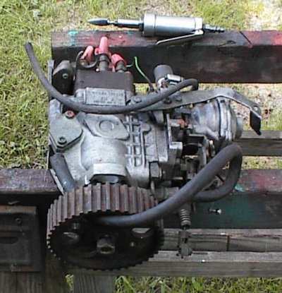 Right side of Bosch Diesel pump. This is a pretty fancy rig, from a turbo
Diesel. It has boost enrichment compensation, EGR offset, an engine
temperature offset, and some other stuff, mostly for smog purposes.
Right side of Bosch Diesel pump. This is a pretty fancy rig, from a turbo
Diesel. It has boost enrichment compensation, EGR offset, an engine
temperature offset, and some other stuff, mostly for smog purposes.
 Driver's side of pump. The BMW used a special belt that had serpentine
grooves on one side, to drive the accessories, and Gilmer teeth on the other,
to drive the cam and injection pump. I'm replacing it with an ordinary Gates
industrial belt.
Driver's side of pump. The BMW used a special belt that had serpentine
grooves on one side, to drive the accessories, and Gilmer teeth on the other,
to drive the cam and injection pump. I'm replacing it with an ordinary Gates
industrial belt.
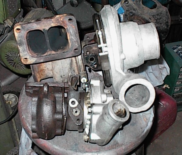 Dual inlets visible here. Some exhaust manifold fangleage will be required to
turn the 4/2 manifold into a 3/3.
Dual inlets visible here. Some exhaust manifold fangleage will be required to
turn the 4/2 manifold into a 3/3.
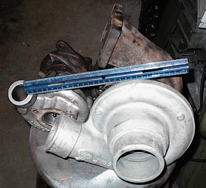
 Note the volume in front of the compressor wheel, and the short snout into the
volume. I'm not sure why it's like that; it looks like it would hurt flow.
On the other hand, it's very nice when you're feeding fuel upstream, since any
liquid fuel would be trapped by the torus and wouldn't get to the compressor
wheel.
Note the volume in front of the compressor wheel, and the short snout into the
volume. I'm not sure why it's like that; it looks like it would hurt flow.
On the other hand, it's very nice when you're feeding fuel upstream, since any
liquid fuel would be trapped by the torus and wouldn't get to the compressor
wheel.
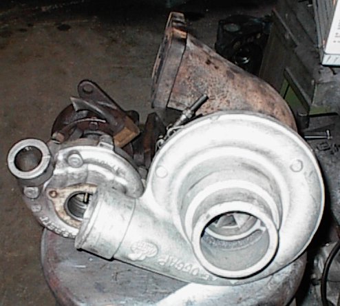
 BIG compressor wheel. Little turbo is from a 2.2 Chrysler.
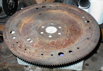 300-Six flexplate for an AOD. The 300 flexplate is identical to a 302
flexplate, except it's zero balance.
300-Six flexplate for an AOD. The 300 flexplate is identical to a 302
flexplate, except it's zero balance.
 Buick cam and crank position sensors for the '148 engine management system.
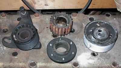 BMW crank sprocket and idler pulleys. One is aluminum, the other plastic, for
whatever weird Kraut reason.
BMW crank sprocket and idler pulleys. One is aluminum, the other plastic, for
whatever weird Kraut reason.