On this project, I'm also scratchbuilding an IR intake, a custom oil pan, and custom headers. I even built the flywheel from scratch!
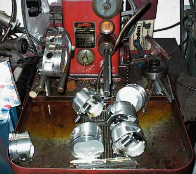
It's not finished so there aren't a lot of details yet, but here's a snapshot of the work in progress.
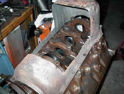
The main difference between the FMX 400 and the 351C is the deck height - 9.2" on the 351C, 10.2" on the 400. The extra inch of deck height allows a substantial increase in stroke compared to the 351C while keeping a good rod ratio. The FMX block will bolt right up to the Pantera's ZF transaxle, the special Pantera accessory brackets will fit, and so forth. The motor mounts on the 351M/400 are unique, but there are semifinished bosses on the FMX block to take 351C style mounts.
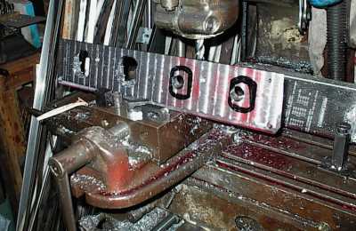
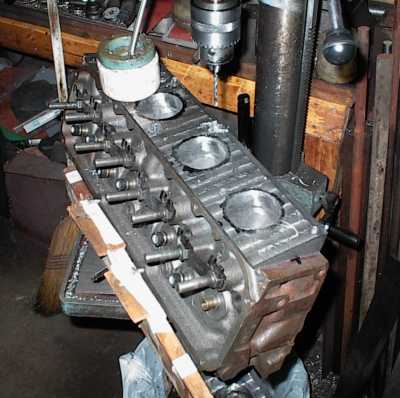
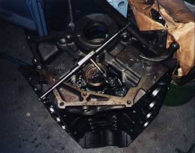
 You can see one of the undrilled Windsor-style motor mount bosses here, and a
mystery boss that might have been intended for some sort of starter support.
You can see one of the undrilled Windsor-style motor mount bosses here, and a
mystery boss that might have been intended for some sort of starter support.
note: the block is upside-down
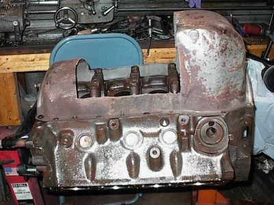
 The infamous "FMX block" casting number. This particular block did time in a
Mustang before the previous owner ventilated a cylinder wall.
The infamous "FMX block" casting number. This particular block did time in a
Mustang before the previous owner ventilated a cylinder wall.
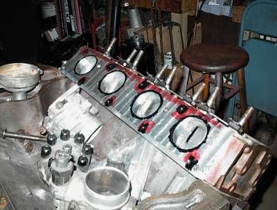
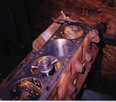 FMX blocks are hard to come by, so I repaired this one. First step is to bore
the cylinder oversize for a repair sleeve. Since I was going .080 oversize, I
used a 390 sleeve, which gives a thicker wall when bored that far. The white
dots are grease from the sonic check probe.
FMX blocks are hard to come by, so I repaired this one. First step is to bore
the cylinder oversize for a repair sleeve. Since I was going .080 oversize, I
used a 390 sleeve, which gives a thicker wall when bored that far. The white
dots are grease from the sonic check probe.
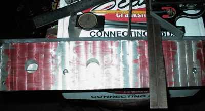
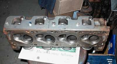
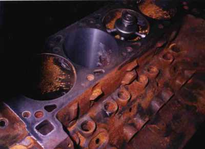 View from the other end. The cylinder is thinner at the sides and bottom.
Or, rather, thicker on the thrust and opposite sides. Most cylinder walls are
thinner at the bottom; that's so the sand cores can be removed easily from
their patterns during the casting process. Blocks are cast upside down, by
the way.
View from the other end. The cylinder is thinner at the sides and bottom.
Or, rather, thicker on the thrust and opposite sides. Most cylinder walls are
thinner at the bottom; that's so the sand cores can be removed easily from
their patterns during the casting process. Blocks are cast upside down, by
the way.
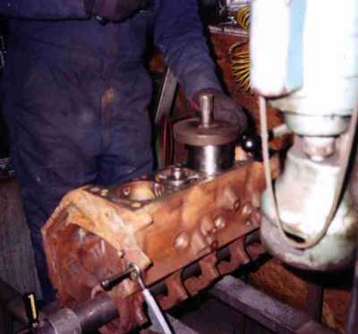 High tech operation in progress! Mandrel and Big Fscking Hammer drive the
sleeve in with .005" interference. The first few inches are easy enough...
High tech operation in progress! Mandrel and Big Fscking Hammer drive the
sleeve in with .005" interference. The first few inches are easy enough...
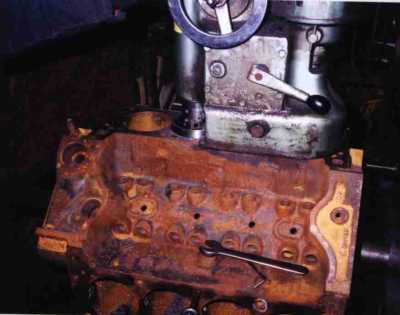 Special bit on the boring bar lets us trim the sleeve flush with the top of
the deck. The sleeve is almost invisible, and no deck surfacing is required.
Special bit on the boring bar lets us trim the sleeve flush with the top of
the deck. The sleeve is almost invisible, and no deck surfacing is required.
That's just surface rust from sitting on the floor in a high humidity area.
(the whole state of Arkansas...) A few hours with the wire wheel took care of
all that.
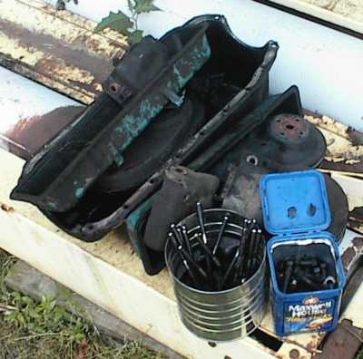 Hardware from a 351M I bought for parts. Since I was starting with a bare
block, I needed various fasteners, cam retainer plate, oil pan, etc.
Hardware from a 351M I bought for parts. Since I was starting with a bare
block, I needed various fasteners, cam retainer plate, oil pan, etc.
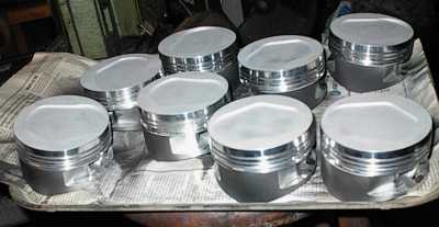
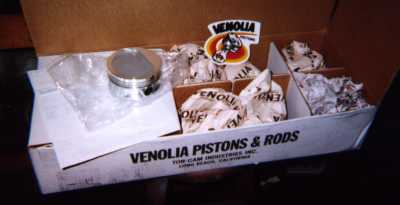 $650 worth of shiny-new custom Venolia forgings. They have the .975" 240 pin
size, CNC-machined dishes to match closed chamber 4V Cleveland heads, and will
give a compression ratio of 10:1.
$650 worth of shiny-new custom Venolia forgings. They have the .975" 240 pin
size, CNC-machined dishes to match closed chamber 4V Cleveland heads, and will
give a compression ratio of 10:1.
 Venolia doesn't include any wristpin lube holes. They don't finish the
wristpin bores to size, nor do they provide wristpins as part of their basic
price. I have some new 390FE pins that will work fine.
Venolia doesn't include any wristpin lube holes. They don't finish the
wristpin bores to size, nor do they provide wristpins as part of their basic
price. I have some new 390FE pins that will work fine.
Here, I've center-punched to drill for four Cosworth-style oil holes.
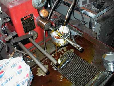 Now I carefully hone the pin bores to the correct fit for the wristpins...
 ...and I'm done. When you're honing aluminum, the difference between correct
fit and too loose is only a couple of strokes over the mandrel.
...and I'm done. When you're honing aluminum, the difference between correct
fit and too loose is only a couple of strokes over the mandrel.
 Clean solvent, soap, water, and air dry.
 Next I sandblast the pistons for ceramic coating. I've already blasted and
coated the sides with moly coating.
Next I sandblast the pistons for ceramic coating. I've already blasted and
coated the sides with moly coating.
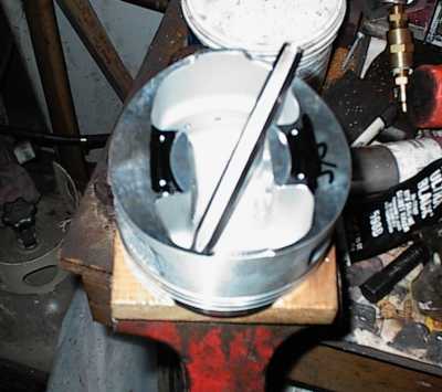
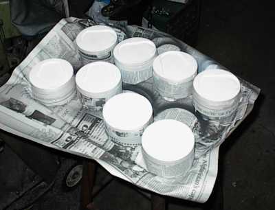 Mask, and shoot the ceramic with the spray gun...
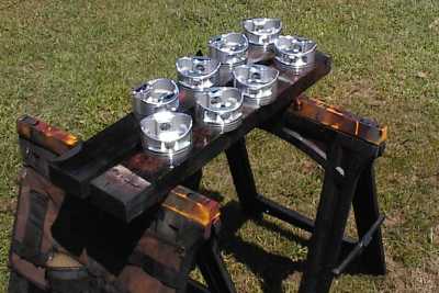
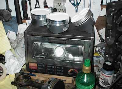 Then bake at 350F. The piston on the right is an ordinary 302 casting for a
different project.
Then bake at 350F. The piston on the right is an ordinary 302 casting for a
different project.
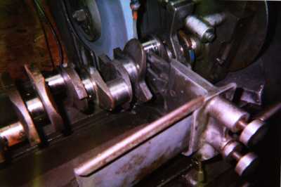
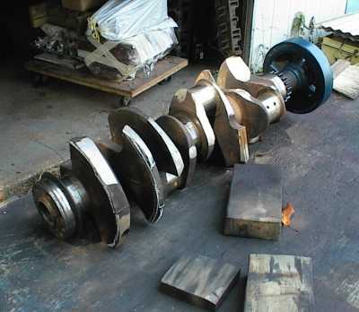
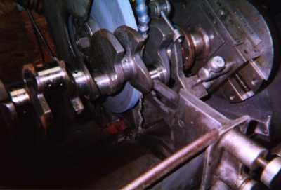 Here I am, set up on a rod throw and chowing down. We're cutting almost a
quarter of an inch off the journal, so it takes a while.
Here I am, set up on a rod throw and chowing down. We're cutting almost a
quarter of an inch off the journal, so it takes a while.
 The grinding wheel is narrower than the journal. The left side is down to a
hair over 240 size and the right is at the stock 400 size.
The grinding wheel is narrower than the journal. The left side is down to a
hair over 240 size and the right is at the stock 400 size.
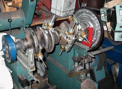
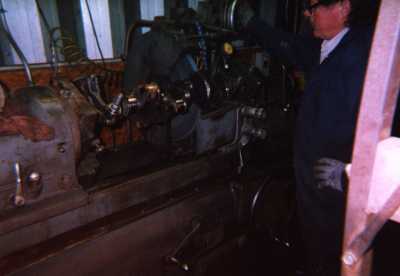 I'm using the crank grinder at my friend Kenney's shop. I don't use the
grinder often, and zeroing in on the final diameter is very much a manual
skill. Rather than sweating bullets each time, I call Kenney over and have
him finish the cut. He thinks it's funny, but he grinds cranks every day.
I'm using the crank grinder at my friend Kenney's shop. I don't use the
grinder often, and zeroing in on the final diameter is very much a manual
skill. Rather than sweating bullets each time, I call Kenney over and have
him finish the cut. He thinks it's funny, but he grinds cranks every day.
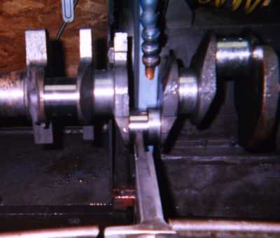
 Finished journal riding on the steady rest.
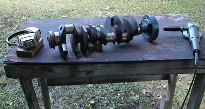
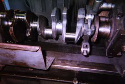 And voila'! A stroker crank. The journals get polished next, using a special
high speed belt.
And voila'! A stroker crank. The journals get polished next, using a special
high speed belt.
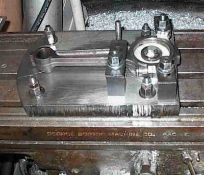 Narrowing a 240 Six rod on the special mill fixture. Holding the rod this way
keeps it from trying to scoot around on the mill table; there's not much to
grab onto that's not in the way of the cutter.
Narrowing a 240 Six rod on the special mill fixture. Holding the rod this way
keeps it from trying to scoot around on the mill table; there's not much to
grab onto that's not in the way of the cutter.
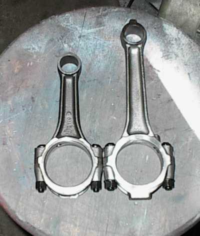 On the left, a 5.0 connecting rod. On the right, a 240 Six connecting rod,
with the big end narrowed and ARP bolts installed. The stock 400 rod is
shorter than the 240 rod, though.
On the left, a 5.0 connecting rod. On the right, a 240 Six connecting rod,
with the big end narrowed and ARP bolts installed. The stock 400 rod is
shorter than the 240 rod, though.
Remember, even though the 400 has the same deck height as a 460, it's still a
small block... lots of room in there for big strokes and long rods.
I decided to make one from scratch. By the time I was done, I had close to $300 in it. Then a new company shows up selling aluminum flywheels for $275. [sigh] Another "learning experience."
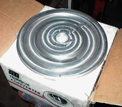
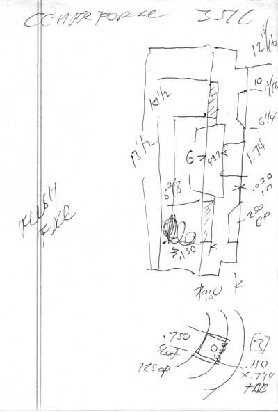 I just happened to have several aluminum flywheels of the correct
configuration on hand, but they all belonged to customers. I measured them
all. This one is a Centerforce.
I just happened to have several aluminum flywheels of the correct
configuration on hand, but they all belonged to customers. I measured them
all. This one is a Centerforce.
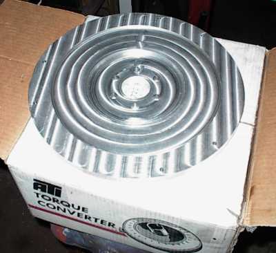
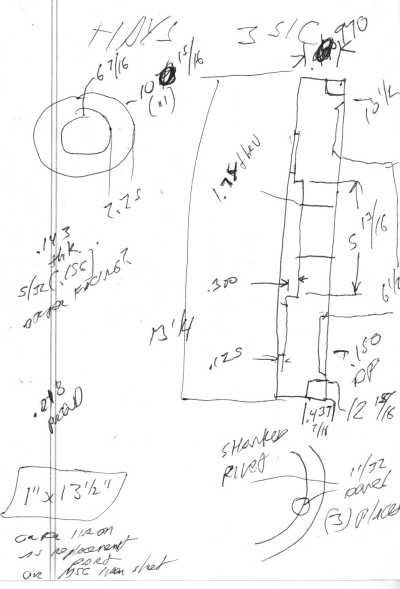 This one is a Hays. I have some other sketches in one of the piles somewhere.
There were minor variations with all of them, but no big deal.
This one is a Hays. I have some other sketches in one of the piles somewhere.
There were minor variations with all of them, but no big deal.
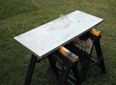
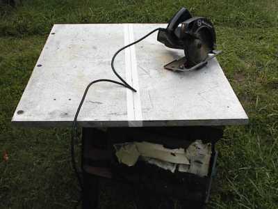 First you take a card-table-sized hunk of one inch aluminum plate, heave it up
onto some sawhorses without straining anything (or, at least only temporarily)
and haul out Mr. Circular Saw. You can cut aluminum with an ordinary carbide
blade.
First you take a card-table-sized hunk of one inch aluminum plate, heave it up
onto some sawhorses without straining anything (or, at least only temporarily)
and haul out Mr. Circular Saw. You can cut aluminum with an ordinary carbide
blade.
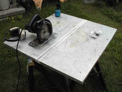 Here I've made it 3/4 of the way through. I took a break every few inches to
let the saw cool; it's not really designed for long cuts in metal. The blue
bottle is full of soapy water I sprayed on the blade as I went, to keep it
from getting hot. If it gets too hot, aluminum will stick to it and it won't
cut any more. It helps to have an assistant to work the sprayer.
Here I've made it 3/4 of the way through. I took a break every few inches to
let the saw cool; it's not really designed for long cuts in metal. The blue
bottle is full of soapy water I sprayed on the blade as I went, to keep it
from getting hot. If it gets too hot, aluminum will stick to it and it won't
cut any more. It helps to have an assistant to work the sprayer.
Why, yes. A circular saw biting into one inch aluminum plate is LOUD.
 The plate sawed in half. It got cut again, into two foot-square chunks. For
some reason I didn't take a picture of that.
The plate sawed in half. It got cut again, into two foot-square chunks. For
some reason I didn't take a picture of that.
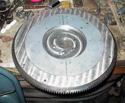
 And it's back! This is the engine side.
 ...and this is the clutch side. Kendall had access to a digital measuring
unit, so I sent him an old clutch cover and the flywheel flange that I hacked
off an old crank, and he got the dimenesions from those.
...and this is the clutch side. Kendall had access to a digital measuring
unit, so I sent him an old clutch cover and the flywheel flange that I hacked
off an old crank, and he got the dimenesions from those.
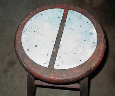
 The friction surface was supposed to be an 11" steel disc. Unfortunately, I
couldn't buy an appropriately sized piece of .125" cold-rolled steel, cast
iron, or bronze at any reasonable price. So I made a two-piece friction
surface from two 6" wide pieces. It's not the usual thing, but segmented
clutch discs work fine, you know.
The friction surface was supposed to be an 11" steel disc. Unfortunately, I
couldn't buy an appropriately sized piece of .125" cold-rolled steel, cast
iron, or bronze at any reasonable price. So I made a two-piece friction
surface from two 6" wide pieces. It's not the usual thing, but segmented
clutch discs work fine, you know.
Here, I'm figuring where to put the welds so they won't be on the finished
pieces.
 Here, I've cut, deburred, and tack welded the pieces together.
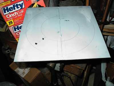
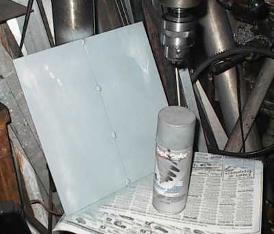 Some gray primer to lay out with. You can lay out with machinist's ink and a
scribe, but you can use an ordinary pencil or pen, or even a scribe, with
spray paint.
Some gray primer to lay out with. You can lay out with machinist's ink and a
scribe, but you can use an ordinary pencil or pen, or even a scribe, with
spray paint.
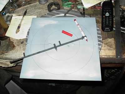 I used my drafting tools to lay out the concentric circles.
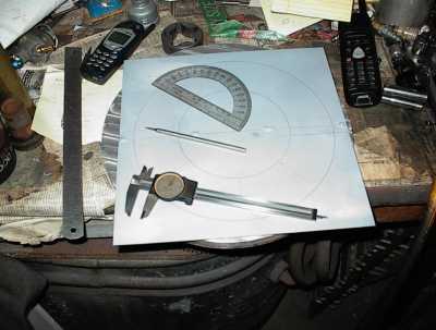
 Here I'm laying out the radial lines for the retainer bolts. The finished
disc will be bolted to the aluminum part of the flywheel. You don't see that
much any more, but it used to be pretty common.
Here I'm laying out the radial lines for the retainer bolts. The finished
disc will be bolted to the aluminum part of the flywheel. You don't see that
much any more, but it used to be pretty common.
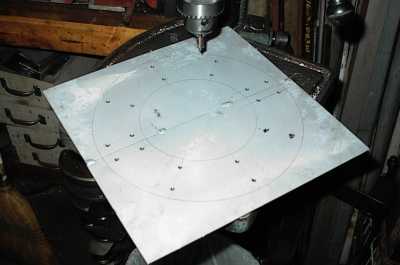 Drilling and countersinking the holes. I'll be using #10-24 countersunk
screws.
Drilling and countersinking the holes. I'll be using #10-24 countersunk
screws.
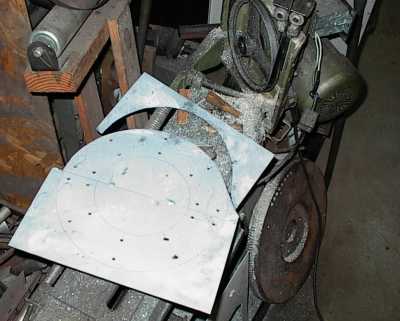 Next, I used my bandsaw to cut the OD. With a fine-tooth blade it only took
five minutes or so.
Next, I used my bandsaw to cut the OD. With a fine-tooth blade it only took
five minutes or so.
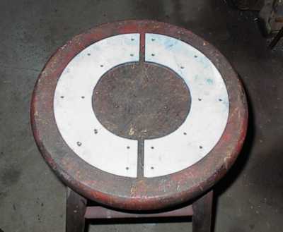
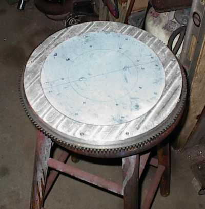 Rough-sawed disc sitting on flywheel. I used the disc sander to dress the
edges down to the pencil line and the disc dropped right in.
Rough-sawed disc sitting on flywheel. I used the disc sander to dress the
edges down to the pencil line and the disc dropped right in.
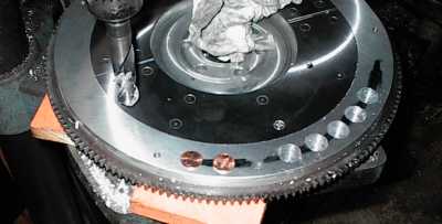
The ring gear is a standard Pioneer replacement part. It's about a .030"
shrink fit, and it required use of air tools to install even when smoking hot.
 ...then you grab one side in each hand and break the tack welds! The welds
were shallow and only on one side, so it was a lot easier than it looked.
...then you grab one side in each hand and break the tack welds! The welds
were shallow and only on one side, so it was a lot easier than it looked.
 I wasn't expecting the bandsaw to be able to cut such a tight inside radius,
but it worked just fine.
I wasn't expecting the bandsaw to be able to cut such a tight inside radius,
but it worked just fine.
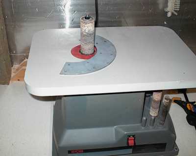 My Dad's spindle sander in his woodworking shop dressed the inside edges to the
pencil lines.
My Dad's spindle sander in his woodworking shop dressed the inside edges to the
pencil lines.
 The discs sitting in their recess. Yes, the gap is supposed to be there. I
wanted to leave a little room for thermal expansion if it got hot
The discs sitting in their recess. Yes, the gap is supposed to be there. I
wanted to leave a little room for thermal expansion if it got hot
 I didn't plan far enough ahead. I wanted to use through bolts with nuts to
hold the friction surface to the flywheel. However, the inner row of bolt
holes came out in a radius on the back side. I could have spotfaced it to
take nuts, but I went ahead and used Heli-Coils instead.
I didn't plan far enough ahead. I wanted to use through bolts with nuts to
hold the friction surface to the flywheel. However, the inner row of bolt
holes came out in a radius on the back side. I could have spotfaced it to
take nuts, but I went ahead and used Heli-Coils instead.
The outer row is tapped and has Nylok nuts on the back. Both rows have
Loctite threadlocker as well.
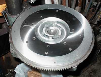 Nearly finished. I hit every hardware store within ten miles, and still came
up short of the required number of #10-24x1" countersunk socket head cap
screws, so I used two Phillips head cap screws to finish up.
Nearly finished. I hit every hardware store within ten miles, and still came
up short of the required number of #10-24x1" countersunk socket head cap
screws, so I used two Phillips head cap screws to finish up.
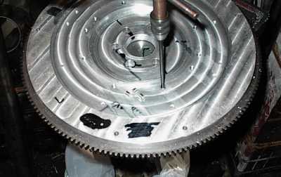
I took the flywheel to a buddy's shop and he used his flywheel grinder to
surface it. Everything was true within .001" or so; it only took a few
thousandths to clean everything up.
 Balancing. Instead of adding weights, I'm removing weight. Aluminum is
light, so you have to remove a lot of it. Which is fine when it's along the
OD; it'll make the flywheel have less rotating inertia. I laid the coins down
to help visualize where the next holes needed to be. The holes are spaced to
allow extra metal near the pressure plate mounting points.
Balancing. Instead of adding weights, I'm removing weight. Aluminum is
light, so you have to remove a lot of it. Which is fine when it's along the
OD; it'll make the flywheel have less rotating inertia. I laid the coins down
to help visualize where the next holes needed to be. The holes are spaced to
allow extra metal near the pressure plate mounting points.
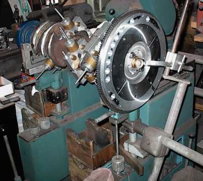 Finished, on the crank for a final verification spin.
Cruising around the salvage yards I found that mid '80s Buick V6s had some 2- 3/8" bore throttle bodies that looked like that might work after removing all the unwanted bits from them. So now I needed a manifold...
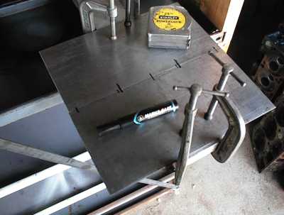
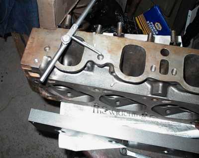
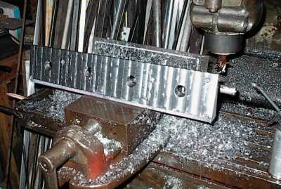
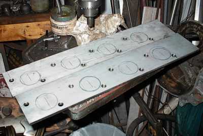
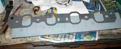 I decided to do it the traditional way. Take some steel plates and mark out
the pattern with a 351C intake gasket...
I decided to do it the traditional way. Take some steel plates and mark out
the pattern with a 351C intake gasket...
 ...drill some holes for the end mill to fit through...
 ...mill the rough openings by hand...
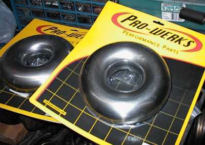 ...and here are the tight-radius 2-3/8" steel donuts. These are very cool,
made from a left and right half that are stamped and welded together.
...and here are the tight-radius 2-3/8" steel donuts. These are very cool,
made from a left and right half that are stamped and welded together.
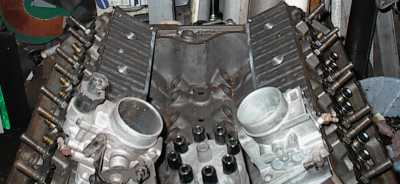
I had the heads and distributor in the bare block, and was playing with a pair of throttle bodies, holding them up and trying to figure out a reasonable way to run the intake tubing. Then I noticed I could just sit the throttle bodies right down on the heads, and everything would clear if I just tilted them a little. I looked down the bores and ports, and things looked like they lined up nicely. Hmmm. Very hmmm.
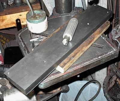
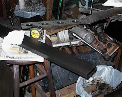 A $60 piece of 1 x 3-1/2" cold rolled steel bar.
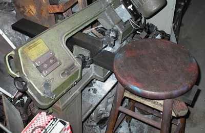 Whack it in half on the bandsaw. Rungs in the stool will keep the cut-off
part from slamming into the floor when the blade makes it through.
Whack it in half on the bandsaw. Rungs in the stool will keep the cut-off
part from slamming into the floor when the blade makes it through.
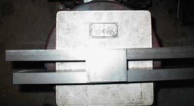 Two pieces, trimmed to the correct lengths, 42 pounds.
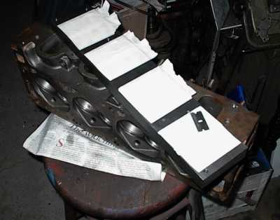
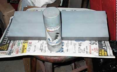 A coat of all-purpose layout chemical...
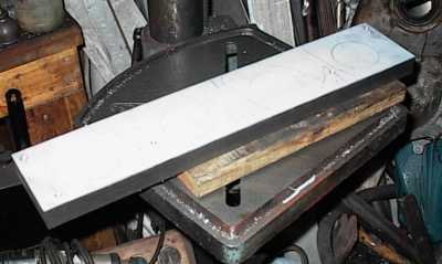 Marking the port openings and the bolt holes. The plates will be permanently
bolted to the Cleveland heads. The attachment bolts need to clear the
throttle body holes, etc.
Marking the port openings and the bolt holes. The plates will be permanently
bolted to the Cleveland heads. The attachment bolts need to clear the
throttle body holes, etc.
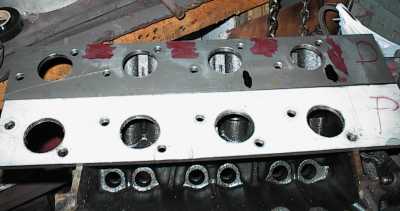
 Drilled through, cleaning up burrs on the back side. If you look you'll
notice there aren't many attaching holes. The plate will be plenty thick and
torqued down firmly, so I don't expect any air leaks. The Cleveland doesn't
pass water through the intake/head junction.
Drilled through, cleaning up burrs on the back side. If you look you'll
notice there aren't many attaching holes. The plate will be plenty thick and
torqued down firmly, so I don't expect any air leaks. The Cleveland doesn't
pass water through the intake/head junction.
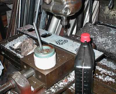
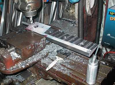
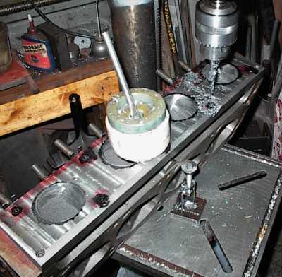
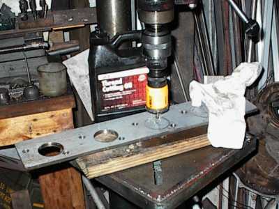
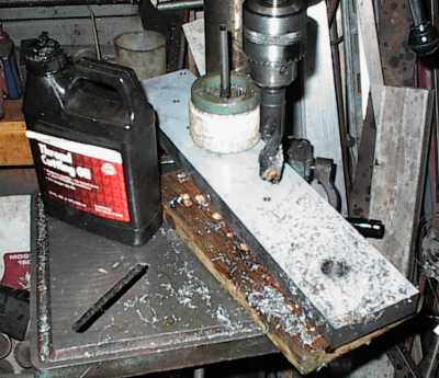 Drilling pilot holes for milling the throttle body openings. You can use a
center-cutting end mill for that, but it's hard on the end mill, and it's
faster to just drill.
Drilling pilot holes for milling the throttle body openings. You can use a
center-cutting end mill for that, but it's hard on the end mill, and it's
faster to just drill.
 Driving a 1" bit through 1" steel is hard on my cheap Chinese drill press. I
had to take a break to replace the bearings in the idler pulley.
Driving a 1" bit through 1" steel is hard on my cheap Chinese drill press. I
had to take a break to replace the bearings in the idler pulley.
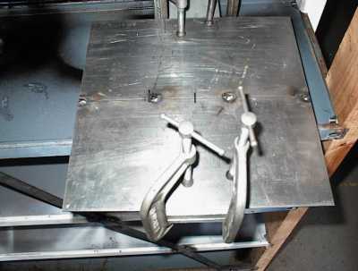
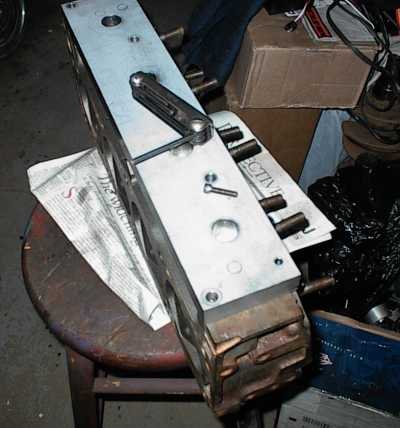
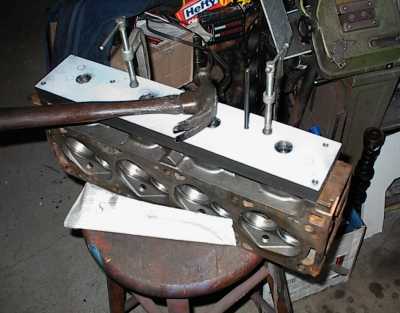 Here, the plate is C-clamped to the cylinder head, and I'm using a transfer
punch to lay out the mounting holes to the head.
Here, the plate is C-clamped to the cylinder head, and I'm using a transfer
punch to lay out the mounting holes to the head.
 After removing the plate, I drilled and tapped the head for the attachment
bolts. I used 5/16-18 socket head cap screws.
After removing the plate, I drilled and tapped the head for the attachment
bolts. I used 5/16-18 socket head cap screws.
 The tape will take an impression of the ports when the adapter is torqued
down. When it comes off, I'll trim with a razor blade, then use a scribe to
mark out the port openings on the adapters.
The tape will take an impression of the ports when the adapter is torqued
down. When it comes off, I'll trim with a razor blade, then use a scribe to
mark out the port openings on the adapters.
 Bolting the adapter plates to the heads to make sure everything is still lined
up right.
Bolting the adapter plates to the heads to make sure everything is still lined
up right.
 Milling time. I worked my way from one end to the other, a bit at a time. It
was a long and tedious job.
Milling time. I worked my way from one end to the other, a bit at a time. It
was a long and tedious job.
 Angle-milled adapter plate! Now to do the other side...
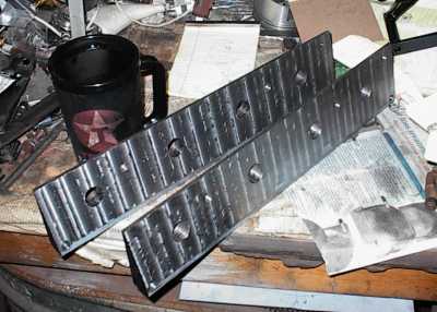 ...and they're done! That step, at least.
 Here's a lousy shot of a throttle body on an adapter. It's just stuck on, not
bolted down yet.
Here's a lousy shot of a throttle body on an adapter. It's just stuck on, not
bolted down yet.
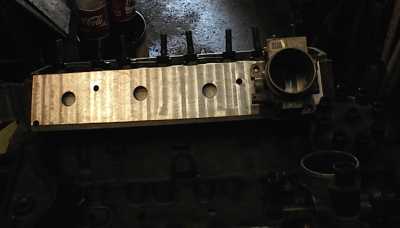
 Another lousy shot, but at least it shows how the plates tilt the throttle
bodies out of the way of the distributor. It didn't take a whole lot, but it
made a big difference!
Another lousy shot, but at least it shows how the plates tilt the throttle
bodies out of the way of the distributor. It didn't take a whole lot, but it
made a big difference!
 Now I need bigger holes for the air to go through. The round throttle body
and oval port mostly match. I'm marking out the locations for both, and I'll
mill out the parts that overlap. The rest I'll whittle out by hand with
the grinder.
Now I need bigger holes for the air to go through. The round throttle body
and oval port mostly match. I'm marking out the locations for both, and I'll
mill out the parts that overlap. The rest I'll whittle out by hand with
the grinder.
 More milling!
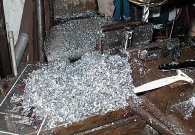 That's how many chips it makes when you open up four holes. That 42 pounds of
steel is down to well under half that, now.
That's how many chips it makes when you open up four holes. That 42 pounds of
steel is down to well under half that, now.
 I've been grinding on the plates for a while. Here I'm taking a break and
drilling and tapping for the throttle body mounting holes. Those will be
5/16-18 UNC.
I've been grinding on the plates for a while. Here I'm taking a break and
drilling and tapping for the throttle body mounting holes. Those will be
5/16-18 UNC.
 Another shot. I used pieces of wood and machinist's jacks to hold the heads
at the correct angle.
Another shot. I used pieces of wood and machinist's jacks to hold the heads
at the correct angle.
 Marked but undrilled head, just seeing how things look...
 .090" steel valley pan and cardboard pattern. This will seal off the lifter
valley.
.090" steel valley pan and cardboard pattern. This will seal off the lifter
valley.
 MPG Head Service exhaust port plates. They get rid of the dogleg in the
exhaust port. The port opening is physically smaller, but the blocked-off
part of the port was dead air anyway.
MPG Head Service exhaust port plates. They get rid of the dogleg in the
exhaust port. The port opening is physically smaller, but the blocked-off
part of the port was dead air anyway.
 I'll be doing custom headers for this engine. The port plates are close
enough to round that I can use round header tubes at the head junctions. That
saves a lot of work. I'm using a pipe size just slightly larger than the
port; the step won't hurt outward flow, and it will slightly impede reverse
flow, which is just fine.
I'll be doing custom headers for this engine. The port plates are close
enough to round that I can use round header tubes at the head junctions. That
saves a lot of work. I'm using a pipe size just slightly larger than the
port; the step won't hurt outward flow, and it will slightly impede reverse
flow, which is just fine.
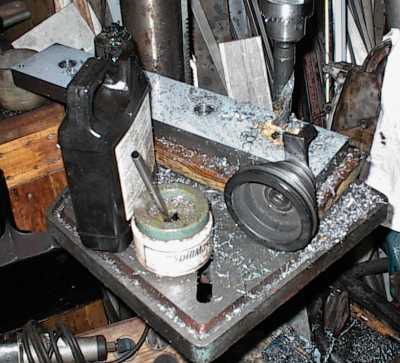
 An ordinary hardware-store hole saw - well, a fancy bimetallic metal-cutting
holesaw - goes right through 5/16 cold rolled steel plate as long as you keep
flooding it with cutting oil.
An ordinary hardware-store hole saw - well, a fancy bimetallic metal-cutting
holesaw - goes right through 5/16 cold rolled steel plate as long as you keep
flooding it with cutting oil.
 Finished header flanges.
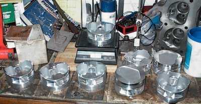 First we balance all the pistons. The Venolias were within a few grams of
each other to start with; I zeroed them up.
First we balance all the pistons. The Venolias were within a few grams of
each other to start with; I zeroed them up.
 The first spin on the balance machine showed a whole lot of weight needed to
come off the counterweights. The 240 rods and Venolias were a lot lighter
than the stock 400 bits. So I started off by knife-edging the counterweights.
This is often counterproductive if a crank isn't too far off to start with,
since it changed the balance quite a bit. In this case, it was so far off it
didn't matter. Mr. Angle Grinder got quite a workout.
The first spin on the balance machine showed a whole lot of weight needed to
come off the counterweights. The 240 rods and Venolias were a lot lighter
than the stock 400 bits. So I started off by knife-edging the counterweights.
This is often counterproductive if a crank isn't too far off to start with,
since it changed the balance quite a bit. In this case, it was so far off it
didn't matter. Mr. Angle Grinder got quite a workout.
 Further along. The corners have been mostly knife-edged, and I'm working on
the OD. Taking metal off the OD is more effective than drilling holes, and it
reduces weight at the perimeter, which reduces the crank's rotational inertia.
Not a lot, but every bit counts. Plus the stock counterweights were severely
football shaped. I'm starting off by grinding them round, which will reduce
windage in the crankcase. And, of course, it all comes off the OD.
Further along. The corners have been mostly knife-edged, and I'm working on
the OD. Taking metal off the OD is more effective than drilling holes, and it
reduces weight at the perimeter, which reduces the crank's rotational inertia.
Not a lot, but every bit counts. Plus the stock counterweights were severely
football shaped. I'm starting off by grinding them round, which will reduce
windage in the crankcase. And, of course, it all comes off the OD.
 Finished balance job, with flywheel. I had to weld a small tab to one edge of
the rearmost counterweight to compensate for the knife-edging. Once I got the
counterweight diameter down to the rod throw diameter I started knife-edging
them so the crank scraper would fit better.
Finished balance job, with flywheel. I had to weld a small tab to one edge of
the rearmost counterweight to compensate for the knife-edging. Once I got the
counterweight diameter down to the rod throw diameter I started knife-edging
them so the crank scraper would fit better.
Right now it's just a rough-ground finish. Later I'll polish it smooth.
 As usual, the pipe plugs in the back of the block had been installed so tight
they simply stripped off when trying to remove them. I've drilled out the
remains, and I'm recutting the tapered threads so new plugs will seal.
As usual, the pipe plugs in the back of the block had been installed so tight
they simply stripped off when trying to remove them. I've drilled out the
remains, and I'm recutting the tapered threads so new plugs will seal.
 The air cutoff wheel made short work of the stock pan.
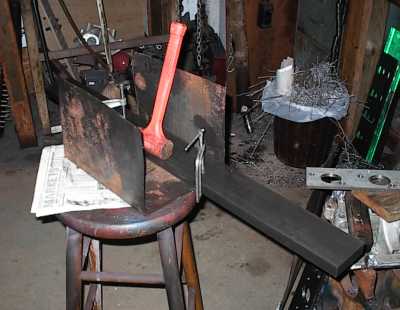
 Notched pan sitting on the block, showing how deep it is in relation to the
main caps. Stock Cleveland pans are very deep by Detroit standards. We could
add a little more depth since the engine sits fairly high in the Pantera
chassis, but I decided not to go too crazy here.
Notched pan sitting on the block, showing how deep it is in relation to the
main caps. Stock Cleveland pans are very deep by Detroit standards. We could
add a little more depth since the engine sits fairly high in the Pantera
chassis, but I decided not to go too crazy here.
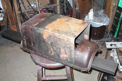
 Different angle. Compared to something like a 350 Chevy, the Cleveland sump
is enormous.
Different angle. Compared to something like a 350 Chevy, the Cleveland sump
is enormous.
 The steel bar I bought for the intake adapters was convenient, so I used it as
a form to bend the 18-gauge steel. I didn't have access to a metal brake, so
I used clamps and a dead-blow hammer. It takes more time, but it will make a
clean bend as long as you don't get carried away and beat dents all along the
bend line.
The steel bar I bought for the intake adapters was convenient, so I used it as
a form to bend the 18-gauge steel. I didn't have access to a metal brake, so
I used clamps and a dead-blow hammer. It takes more time, but it will make a
clean bend as long as you don't get carried away and beat dents all along the
bend line.
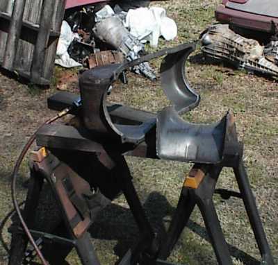
 The new sump in position. I need to hammerform the cut-off area of the stock
pan a little to reduce the amount of welding needed, and I still need to make
the back panel.
The new sump in position. I need to hammerform the cut-off area of the stock
pan a little to reduce the amount of welding needed, and I still need to make
the back panel.
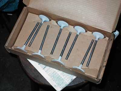 All the valves were sandblasted and ceramic thermal barrier coated on both
sides. These are the exhaust valves, before polishing.
All the valves were sandblasted and ceramic thermal barrier coated on both
sides. These are the exhaust valves, before polishing.
All the valves are 5/16" stem instead of the stock 11/32".
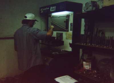 I took the heads to Kuntz & Co. and they ran them on their flow bench. I used
the numbers to select a camshaft. Contrary to popular belief, the 4V
Cleveland heads have excellent low lift flow. Since this is a street engine,
I couldn't see beating up the valvetrain with more lift than necessary.
I took the heads to Kuntz & Co. and they ran them on their flow bench. I used
the numbers to select a camshaft. Contrary to popular belief, the 4V
Cleveland heads have excellent low lift flow. Since this is a street engine,
I couldn't see beating up the valvetrain with more lift than necessary.
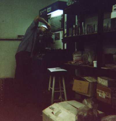 Grainy shot is from a scan from a disposable 35mm camera.