brought to you by: Dave Williams
This page: www.bacomatic.org/~dw/fordv8/fe/fe.htm
Main page:
http://www.bacomatic.org/~dw/index.htm
Last Updated: 18 Sep 2003
Author: Dave Williams; dlwilliams=aristotle=net
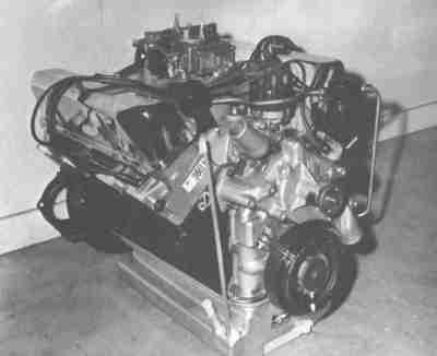 This picture is from 1966; the original caption said it was "the lightweight
high-performance unit with alloy heads and front cover plate as used in the
427 Cobra." All FEs had the aluminum front cover, but this one appears to
have an aluminum water pump as well as the aluminum heads. Note the low rise
dual plane intake and the fancy oil pan, which appears to be aluminum. It's
definitely not a Cobra engine; perhaps it was a GT40 development engine?
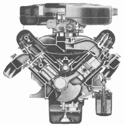 This is a solid-lifter engine, probably passenger car from the low profile air
filter, probably a 390. Note the simple box exhaust manifolds. Everyone
likes to look at the fancy sweeping hipo cast headers, but they were always
rare. 99% of all FEs got these restrictive iron logs.
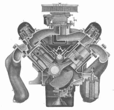 This is an early solid lifter engine with the oval aluminum air cleaner, large
sweeping exhaust manifolds, and cross-bolt mains. It's probably a 427,
judging by the short stroke and large bore.
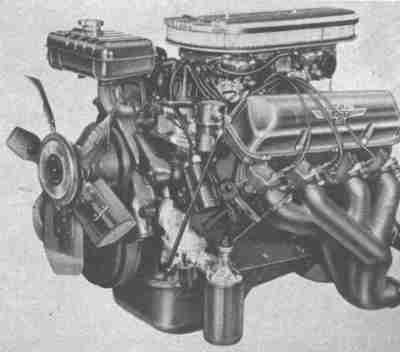 This is what the above engine would look like all dressed up and ready to go.
Those fill/surge tanks command very high prices nowadays. Note the exhaust
manifold is actually a tri-Y design.
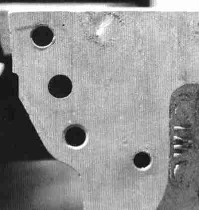 The FE's oiling system verges on the bizarre. The "maze of twisty little
passages" starts right at where the oil pump bolts to the block - the hole is
half the size of the pump outlet and makes an instant right-angle turn. It
seemed to work just fine for Ford, but almost everybody else enlarges the hole
to match the pump and reaches inside with a small ball cutter to radius the
junction with the oil passage to the filter adapter.
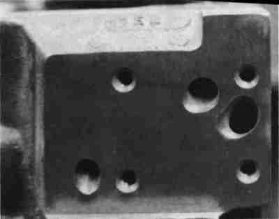 Things don't get any better at the oil filter adapter. This block has been
radiused to try to smooth the oil flow some.
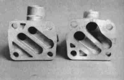 Regular FE oil filter adapter on the left. 427 adapter on the right. The 427
adapter flows a bit better inside, but both are still much larger than the
holes in the block! The regular adapter will do fine; either needs a hot date
with the die grinder though.
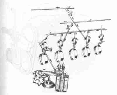 This is the *simple* FE oil system - the early solid lifter engines didn't
even bother to oil the lifters directly. They worked just fine with splash.
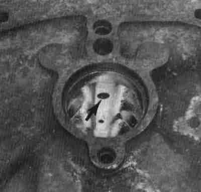 Just for variety, '61-'62 390 HP, 406, and '63-early '65 427s used an oil
pressure relief valve at the end of the main oil gallery. You're looking at
the back of the block up through the rear cam bearing. The 'ears' at the top
of the bearing flange are where the drillings would be to feed hydraulic
lifters. The small plug at the bottom is for the drillings to the rear main
bearing; the rear main's oilways jog forward since the rear cam bearing isn't
directly over the main bearing.
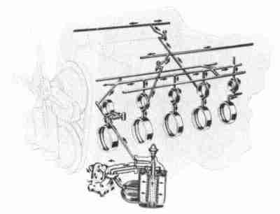 This maze of twisty little passages was drilled into all hydraulic lifter FEs,
and all FTs. Not only that, there are about a dozen cup or pipe plugs to trap
the unwary rebuilder. Miss one and you won't get any oil pressure.
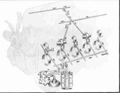 And here's how the famous side oiler is laid out. This is an early solid
lifter version. The oil pressure relief valve is at the rear of side side oil
passage to ensure full oil pressure throughout the system.
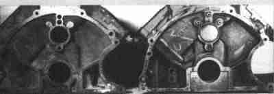 This picture is a little dark but you can make it out. The block on the right
is a side oiler. The block on the left was *cast* as a side oiler, but it was
drilled as a top-oiler. Blocks like this show up frequently as ordinary low
performance 360s and 390s. Don't get too excited if you find one - drilling a
straight hole two feet deep isn't something you can do without special
equipment.
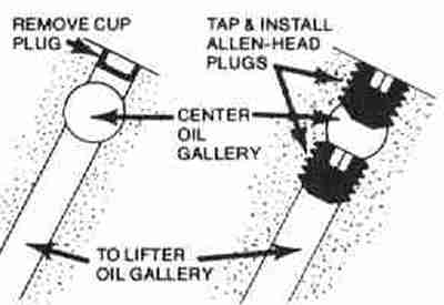 Of course, you can only use a hydraulic lifter cam in a block drilled for
hydraulic lifter oiling. You can slide a solid cam right into a hydraulic
block, though. Ford recommends blocking the oil passages to the hydraulic
lifters to help maintain oil pressure. *Always check* a newly acquired
hydraulic lifter block to make sure someone hasn't already done this, or your
hydraulic lifters won't work!
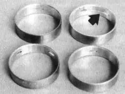 Normal FE cam bearings (arrow, right) have grooves to feed the rocker
shaft oilways. Side oiler bearings (left) do not. You can use the normal
bearings in a side oiler without any harm, though.
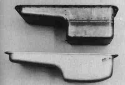 Plain old FE passenger-car pan is below. Top pan is 427 passenger-car pan,
easily identified by the welded-on sump extension.
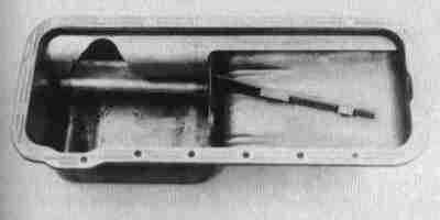 Inside the 427 pan. The baffles aren't complicated; you could make some out
of sheet metal and weld them into an ordinary 390 pan and save the $350 or so
they charge for an aftermarket pan. Note the "collector trough" on the
starter side.
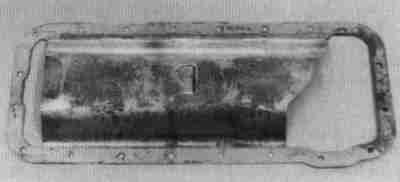 Since the FE's pan rails hang down below the crank centerline the windage tray
doesn't need to be curved much. The tray was used on various high performance
FEs and copies are available through the aftermarket for $35 or so.
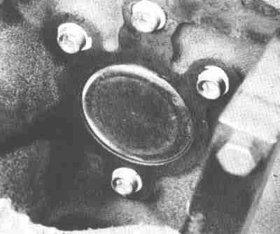 Most FEs have pressed cup plugs in the rear oil galleries. If your engine has
a solid block spacer plate (the sheet metal thingie between the engine and
trans) the spacer will keep the plugs from coming loose. If you have a spacer
with holes where the cup plugs are, you can drill and tap the back of the
block to use screw-in plugs. The problem is, the oil galleries are a weird-
bastard size that doesn't come close enough to any normal pipe plug for it to
be easy to tap NPT, at least if you want more than a suggestion of threads.
This is a Ford Power Products plug kit.
You can tap the galleries 1/2-20 UNF and use 1/2-20 by 3/8" deep set screws, which give plenty of thread. Be sure to use Loctite or a good thread sealer. I also stake the screws in place with a punch.
Note the FE puts the plug at the end of the cam gallery in *backwards*. Many
service manuals don't bother to mention this little detail. First FE I built,
I put it in the wrong way. It's still going as far as I know, but don't make
the same mistake I did!
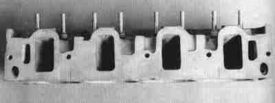 This is one of the famous 427 High Riser heads, special order for the '63 427
under part number C4AE-6049-F. The ports were over 3/4" taller than standard
390 ports to get a better shot at the valve. The valve sizes were enlarged to
2.195/1.733. The High Risers also needed shorter rocker stands and a special
intake manifold. The heads were intended for NASCAR use, but also did
well in drag racing. Your friendly Ford dealer would hit you for $168.55 each
for these in 1971.
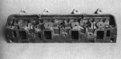 The 427 Medium Riser was introduced after the High Riser. It was a result of
extensive airflow development by Ford's engineering team. The heads on the
racing GT-40s were derived from the Medium Riser. Intake port height is 2.34"
and the Medium Risers will take ordinary FE intake manifolds.
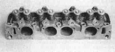 The 427 Tunnel Port heads were more special-order bits; $189.50 each at your
local Ford dealer in 1971. The intake ports were moved directly in line with
the valves instead of bending around the pushrods. The Tunnel Port simply ran
the pushrods through small round tubes. They used a 2.25" intake valve and,
of course, a special intake manifold. The Tunnel Port's exhaust side and
combustion chamber were the same as the Medium Riser.
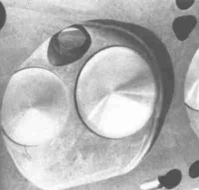 Ford machined the combustion chambers on some high performance engines instead
of just leaving the chamber as-cast. This is a medium riser 427 head. Some
406s also came this way, and I've seen it on an early Edsel 361, so don't
automatically assume heads with machined chambers are the good medium riser
parts.
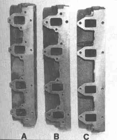 In typical Ford fashion there are several exhaust bolt patterns. The "A" head
is representative of the 428 CJ and some service replacement heads. It has
both the vertical and diagonal patterns. The "B" head is known as the 390 GT
type and is lacking the two center lower bolt holes. The "C" head is the most
common type, used in large cars and in trucks. The diagonal bolt patterns
were usually Mustang and Fairlane. However, most Mustang headers come with
the vertical bolt pattern! The "A" type heads are the most desirable just to
avoid the hassle with headers or manifolds. There's no reason you can't
drill and tap the missing holes to turn "B" heads into "A" heads if you want.
The "C" heads are perfectly acceptable *if* you have manifolds or headers with
that pattern that fit your chassis.
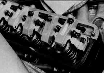 Jesel came out with these rockers in 1993. A large steel adapter plate bolts
to the head and the rockers sit on paired trunnions. The rockers will clear
1.630" springs. Jesel claimed they were good to 12,000 RPM.
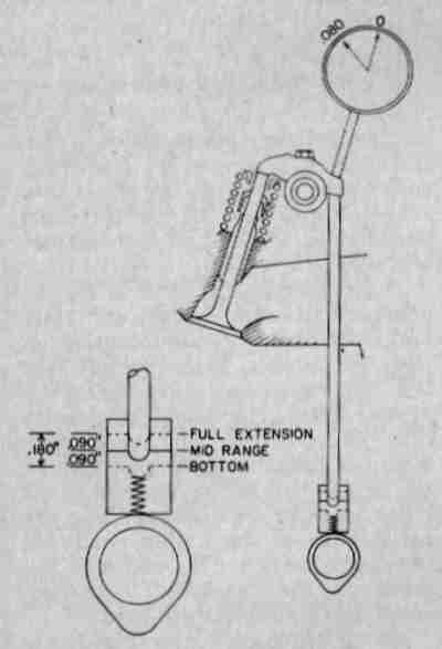 Most hydraulic lifters have an operating range of .060 to .100. The FE uses
special long-travel lifters. Some other Ford lifters will interchange with
the FE parts, but probably won't have enough adjustment range to work right.
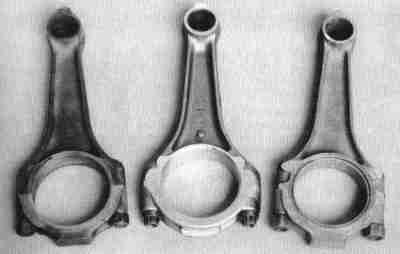 More FE exotica. Plain old 390 passenger car rod on left, 427 Le Mans rod on
right, 427 Low Riser/428 Cobra Jet rod on right.
The 390 rod (C3AZ-6200-F) is the same one used in the 390 High Performance, 390 Police Interceptor (back in the days when there were real differences between those and ordinary cars), the 406, and the '63-'64 427. It has a 3/8" rod bolt.
The center rod is the vaunted 'Le Mans' capscrew rod. It came in the '65-'67
427 Medium Riser and 'special order' '65-'68 427 High Riser. It also came in
the '69-'70 428 Super Cobra Jet under the part number C9ZZ-6200-A with a
different rod bolt for clearance with the 428's quarter inch longer stroke.
The rod bolts (capscrews) thread up from the bottom into the rod shank, which
is tapped to accept them. There are no rod nuts. The Le Mans rod is stronger
and much heavier than the standard rods
The CJ rod (C6AZ-6200-C) has a slightly thicker beam and 13/32" bolts. It came in the '68 427 with the hydraulic cam, the '66-'70 428 Police Interceptor, and the 428 Cobra Jet.
Ford was *serious* about making the 427 and 428 race-ready; don't get the
idea there was anything wrong with the ordinary 390 rod. A prepped 390 rod is
adequate for almost any FE.
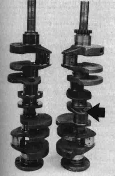 Ordinary cast 390 crank on the left has the same stroke as forged steel 427
competition crank on right. The steel crank has considerably different
oilways than the cast crank. The mains are crossdrilled and the rod throw
lightening holes are plugged and form oil reservoirs. The rod journals oil
holes are then drilled into these reservoirs at about 3 o'clock instead of 1
o'clock. This gives more "wrap" of the oil around the journal before the
point of maximum load and gives the oilways an effectively shorter radius.
Centrifugal force is sufficient to provide oil pressure to the rods above a
fairly low RPM. At racing revs this can pull oil from the mains faster than
the pump can feed it, which makes the mains unhappy.
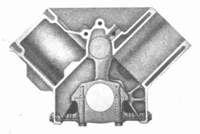 Cutaway of the block. This is a cross-bolt 427, though cross bolts could be
found on 406s and a very few 390s. The skirts hanging down below the crank
centerline are really very thin, on the order of an eighth of an inch. They
probably don't add more than five or six pounds to a non-cross-bolt FE
compared to one with a conventional wrap-around oil pan. In return for the
small weight penalty they let Ford use a simple shallow stamping for the pan
and a one-piece pan gasket instead of two cork pieces and two rubber pieces.
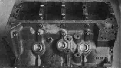 Not all cross-bolt blocks were side-oilers. This block is both; the four pipe
plugs (three are under the cross bolts) seal the outside of the oil gallery
running along the side of the block. Normal FEs oil from the top, around the
cam bearings, like a small block Chevy. Side oilers oil from a gallery above
the pan rail like a big block Chevy.
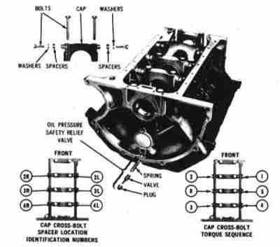 Here's the torque sequence for the cross-bolt blocks.
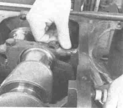 Spacers for the cross-bolt engines were selected to be a light interference
fit.
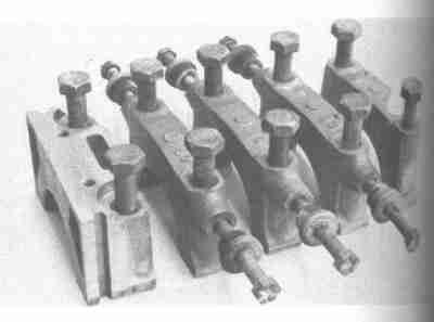 Yes, these are the famous cross-bolt main caps. The way Ford did the skirt
bracing made it impractical to fit conventional four bolt caps, so they
changed the braces a bit and bolted the caps out from the sides into a girdle
arrangement. The spacers are select-fit.
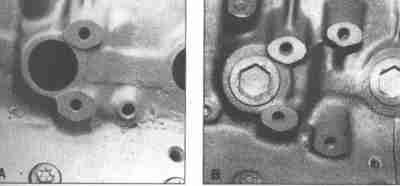 Pre '65 FE engines had only two bolt holes per side for motor mounts. '65 and
later have four, and can accept both early and late mounts. Some truck
applications held the engine by a yoke up front by the lower pulley; these
blocks may have either type of boss cast in the side, but they may not be
machined. Very early truck engines may not even have the bosses. Check to
make sure the block will work with your mounts when buying a new block.
The four-bolt mounts, screw-in core plugs and the bolt heads visible at the
bottoms of the photos indicate this is a later cross-bolt 427 block.
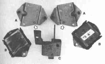 Most Ford engines use a steel bracket on the chassis (C) and a bonded rubber
isolator on the engine (B). The FE has those, plus an extra steel bracket
between the isolator and the block, (A). More than one FE engine swapper has
scratched his head while trying to figure out why the isolator wouldn't bolt
to the block. Sometimes finding the brackets can be time-consuming, so don't
wait until the last minute if you don't have them.
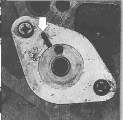 The FE cam thrust plate is very thin. The oiling groove goes to the outside
at 11 o'clock. If you're a 302 guy it can be confusing, since the 302 uses a
similar groove to feed oil to the distributor shaft drilling on the block side
of the plate. Note the Phillips-head screws. The upper left screw blocks the
lifter oil gallery. An impact driver is the easiest way to remove the screws.
Countersunk socket head cap screws can be substituted for the Phillips screws
and you can use an Allen wrench to install and remove them.
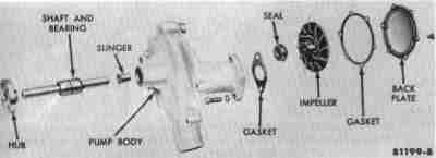 Exploded view of the FE water pump. It's a large iron casting; you can save
ten or fifteen pounds with an aftermarket aluminum pump. Like most pumps it's
theoretically rebuildable, except ordinary schmucks like you and me can't buy
the required parts.
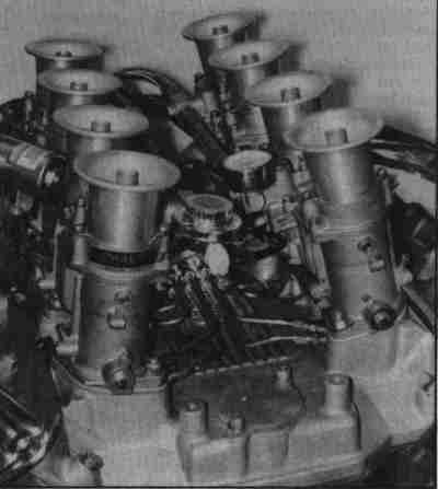 Weber downdrafts were used on many Shelby Cobras and Holman-Moody prepped
GT40s. Inglese still sells everything you need. This particular intake has
been set up for nitrous injection.
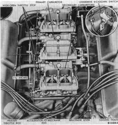 Factory 3x2 setup on a 390. Ford mounted the carburetors backwards and ran
the linkage over to the passenger side. Because, that's why...
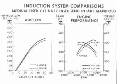 4V vs 8V Medium Riser airflow.
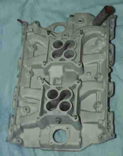 Rare 406-only dual quad intake from Ford.
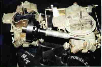 Mickey Thompson cross-ram intake and extended distributor. Very rare, very
trick.
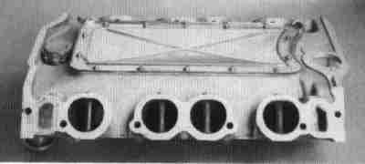 Here are the infamous tunnel ports. In the FE the pushrods run through the
intake, not the cylinder head. The tubes seal against oil and vacuum leaks.
Interestingly enough there were at least three Tunnel Port intakes available -
a high rise 2x4 with air-gap runners, a more conventional low rise 2x4, and a
low rise single four barrel. Ford's 1969 Muscle Parts catalog listed the
single plane at $103.95 and the other two at $172.00.
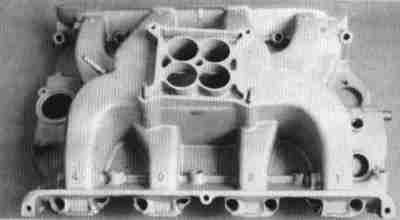 This is a High Riser intake. Both single and dual quad manifolds were
offered from the factory; oddly enough, both were dual plane designs. They're
not hard to identify if you come across one - not only are they visibly taller
than any other dual plane you'll find, the 3" tall runners are easy to spot
too. High Riser intakes were $99.25 for the single carb dual plane, $132.70
for the dual carb dual plane.
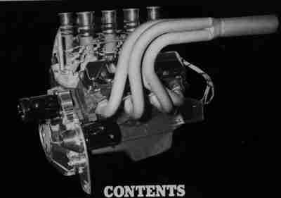 FE set up for marine use; note reverse-rotation starter. The intake manifold
appears to be a Hilborn, but the butterflies are transverse instead of inline.
My Hilborn catalog doesn't show anything like that. Hmm...
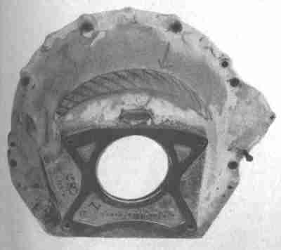 Some 427s, 428s, and large trucks came with a monster 11.5" clutch. The
bellhousings for these had a bulge to clear the pressure plate, shown here
with the pattern marked with a felt tip pen. The bellhousings were
discontinued long ago. If you letch for a monster clutch you'll need to
scrounge for one or go to an aftermarket bellhousing.
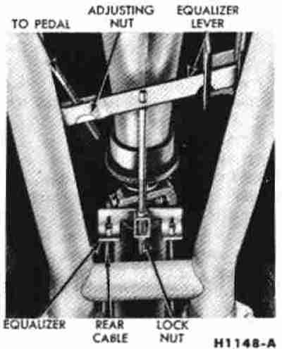 Exhaust pipes from a 1962 Thunderbird. Note the crossover tube.
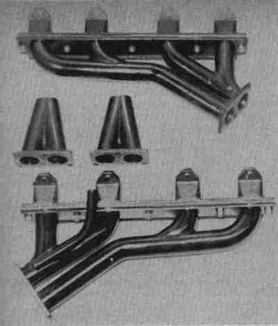 Hedman Hedders for 332 and larger engines in '50s passenger cars. Two-piece
design was marketed as suitable for two or four exhaust pipes.
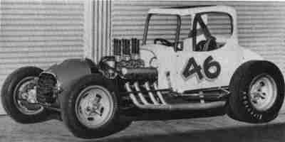 390-powered sprint car, circa 1968.