Miscellaneous Ford Stuff
brought to you by: Dave Williams
This page: www.bacomatic.org/~dw/fordv8/fordmisc/fordmisc.htm
Main page: http://www.bacomatic.org/~dw/index.htm
Last Updated: 16 Jul 2003
Author: Dave Williams; dlwilliams=aristotle=net
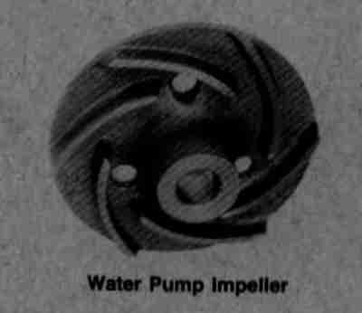 This is the cast iron, curved-vane water pump impeller the old Muscle Parts
catalog recommended for upgrading your racing BOSS 351. It's still in the
catalog as M-8512-A302. I tried to purchase one in 1995. The best price I
could find was around $50. Then I found out there are half a dozen different
housings with different internal shapes; the impeller was designed for the M-
8505-A331 aluminum housing ($150) and there are major differences among the
rest of the small block housings. It's easier just to buy a whole aftermarket
pump with a good impeller instead of a sheet metal paddle.
This is the cast iron, curved-vane water pump impeller the old Muscle Parts
catalog recommended for upgrading your racing BOSS 351. It's still in the
catalog as M-8512-A302. I tried to purchase one in 1995. The best price I
could find was around $50. Then I found out there are half a dozen different
housings with different internal shapes; the impeller was designed for the M-
8505-A331 aluminum housing ($150) and there are major differences among the
rest of the small block housings. It's easier just to buy a whole aftermarket
pump with a good impeller instead of a sheet metal paddle.
 Early rodders often ran dual-fuel setups. This Ford coupe has a 5-gallon
aluminum tank with high-octane racing fuel. Hand-operated plunger pump
pressurizes tank to 6 PSI to ensure positive pressure to get fuel to the main
fuel pump.
Early rodders often ran dual-fuel setups. This Ford coupe has a 5-gallon
aluminum tank with high-octane racing fuel. Hand-operated plunger pump
pressurizes tank to 6 PSI to ensure positive pressure to get fuel to the main
fuel pump.
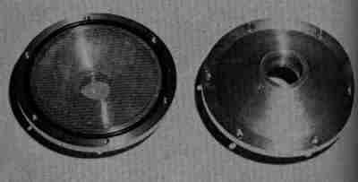 Okay, not a Ford-specific part. This Eelco cleanable oil filter was available
in 1961. It, or copies of it, have been available under half a dozen names
since. I still think that screen is some kind of commonly-available part you
could probably find in a hydraulic shop.
Okay, not a Ford-specific part. This Eelco cleanable oil filter was available
in 1961. It, or copies of it, have been available under half a dozen names
since. I still think that screen is some kind of commonly-available part you
could probably find in a hydraulic shop.
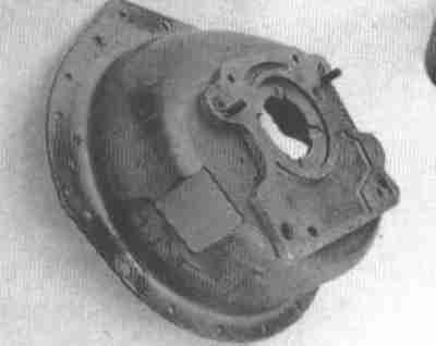
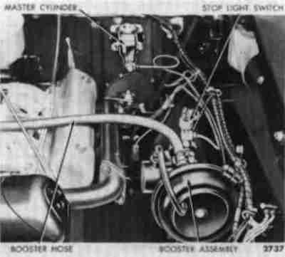 Ford used this remote-mount power brake booster setup in 1957-1959 models.
Many of the remote-booster street rod conversions use these parts.
Ford used this remote-mount power brake booster setup in 1957-1959 models.
Many of the remote-booster street rod conversions use these parts.
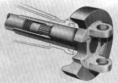 Ford added this harmonic-balancer-style vibration damper to the front yoke of
some models beginning in 1967. The damper was just another step in
controlling what Ford calls "NVH", for "Noise, Vibration, and Harshness."
Ford added this harmonic-balancer-style vibration damper to the front yoke of
some models beginning in 1967. The damper was just another step in
controlling what Ford calls "NVH", for "Noise, Vibration, and Harshness."
 This tool was used for checking transmission misalignment.
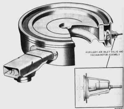 For some reason this is the only picture I can find of a Ford air filter
housing. Ford used this type from the late '60s through the early '80s.
If you're serious about performance, throw away that cheap open-element
filter, run down to the junkyard, and dig one of these babies up. They take
the big 14"x3" air filter element, have large radii at the carb inlet just
like those new carbon-fiber racing filter housings, and large inlet snorkels
already barbed to take ram-air hose, available off-the-shelf at almost any
parts store. Sure, Ford ran the inlet hose to the battery box or beside the
radiator, but you don't have to run it there. Most models have provision for
quick warm-up air coming off the exhaust manifolds.
For some reason this is the only picture I can find of a Ford air filter
housing. Ford used this type from the late '60s through the early '80s.
If you're serious about performance, throw away that cheap open-element
filter, run down to the junkyard, and dig one of these babies up. They take
the big 14"x3" air filter element, have large radii at the carb inlet just
like those new carbon-fiber racing filter housings, and large inlet snorkels
already barbed to take ram-air hose, available off-the-shelf at almost any
parts store. Sure, Ford ran the inlet hose to the battery box or beside the
radiator, but you don't have to run it there. Most models have provision for
quick warm-up air coming off the exhaust manifolds.
The snorkels are riveted on, so you can add an extra if you want... or pick up
one from an early Mustang GT, which had dual snorkels to start with... *and*
they were made out of aluminum and weighed almost nothing.
For some crazy reason people will pay $150 for an aftermarket ram air housing
that's not even near as nice as the factory part.
You might have to do some creative BFH work if you have a Holley with center-
hung float bowls, but it's well worth the effort. Why suck in all that hot
underhood air? Ford did these filter housings *right*.
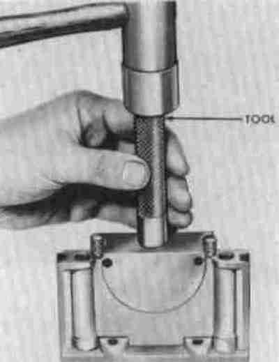
 Ford makes this tool for centering the timing cover on pre-5.0 (non-doweled)
Windsors. Most rebuilders just slide the balancer on as far as it will go by
hand, tighten the cover, then finish installing the balancer.
Ford makes this tool for centering the timing cover on pre-5.0 (non-doweled)
Windsors. Most rebuilders just slide the balancer on as far as it will go by
hand, tighten the cover, then finish installing the balancer.
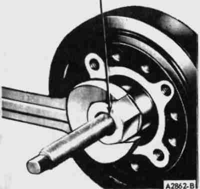 Here's how you're supposed to install the balancer on a Windsor. The
aftermarket didn't pick up on this for quite some years...
Here's how you're supposed to install the balancer on a Windsor. The
aftermarket didn't pick up on this for quite some years...
 According to my 1975 Ford service manuals, Ford's 1975 Mustang II had an
auxiliary fuel tank as standard equipment, and the tank was optional on the
other Mustang II models. Auxiliary tanks were also available on the full-size
cars and wagons. I've never come across any of these, but they're pretty
nifty.
According to my 1975 Ford service manuals, Ford's 1975 Mustang II had an
auxiliary fuel tank as standard equipment, and the tank was optional on the
other Mustang II models. Auxiliary tanks were also available on the full-size
cars and wagons. I've never come across any of these, but they're pretty
nifty.
 Ford had tools similar to this for every engine during the days of rope rear
main seals. You used this mandrel to hammer and shape the rope seal into the
block and cap grooves. You could install the seal with your fingers and
something to roll it in place, but the mandrel had a much better chance of
installing one that wouldn't leak.
Ford had tools similar to this for every engine during the days of rope rear
main seals. You used this mandrel to hammer and shape the rope seal into the
block and cap grooves. You could install the seal with your fingers and
something to roll it in place, but the mandrel had a much better chance of
installing one that wouldn't leak.
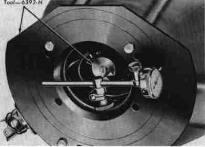
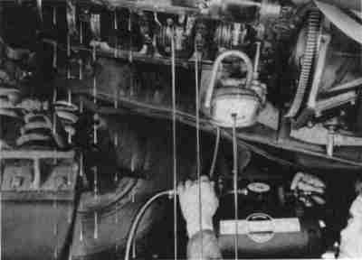 This isn't a Ford engine, and as far as I know Ford never recommended the
procedure, but it's so nifty I thought I'd include it anyway. This is an
engine undergoing an oil leak test. The pan is pulled and oil is forced into
the engine by compressed air. By measuring the side clearances of the
bearings with a feeler gauge and counting the number of drops of oil per
minute, the mechanic could tell the clearance of the rods and mains with a
high degree of accuracy. It looks really Mickey Mouse, but it's the same basic
procedure Ford uses at the factory to test brand new engines and automatic
transmissions.
This isn't a Ford engine, and as far as I know Ford never recommended the
procedure, but it's so nifty I thought I'd include it anyway. This is an
engine undergoing an oil leak test. The pan is pulled and oil is forced into
the engine by compressed air. By measuring the side clearances of the
bearings with a feeler gauge and counting the number of drops of oil per
minute, the mechanic could tell the clearance of the rods and mains with a
high degree of accuracy. It looks really Mickey Mouse, but it's the same basic
procedure Ford uses at the factory to test brand new engines and automatic
transmissions.
The main problem with the leak test nowadays is there are so few cars where
it's practical to get the pan off without having to pull the whole engine out.
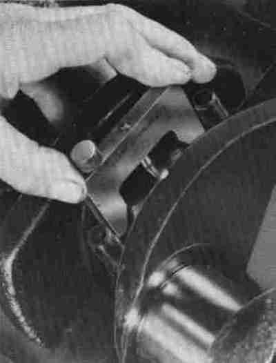 This is a crank journal diameter gauge. Perfect Circle made them at least
through the 1950s. Ford approved of and recommended using them for servicing
Ford engines. Unfortunately Perfect Circle doesn't make them any more, and
I've never managed to quite figure out how they work. It would be a nice tool
to take a quick reading of a journal you can't get a mike to for some reason.
This is a crank journal diameter gauge. Perfect Circle made them at least
through the 1950s. Ford approved of and recommended using them for servicing
Ford engines. Unfortunately Perfect Circle doesn't make them any more, and
I've never managed to quite figure out how they work. It would be a nice tool
to take a quick reading of a journal you can't get a mike to for some reason.
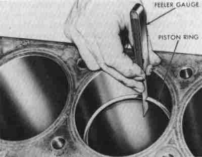 This image is supposed to show you how to check the ring gap, but it will do
as well for showing you another way to check the bore diameter. Procure a
ring in your bore size - most rebuilders will give you all the used rings you
want - and find a block with the same bore as yours; preferably freshly
machined and gauged by the machine shop. It doesn't have to be the same brand
of ring or block, just the same bore size. Insert the ring squarely in the
bore - an old piston works well as a squaring tool - and use your feelers to
check the ring gap. Assuming your block has a bore of 4.030" and your gap is
.029", .029" is your base figure. Since the diameter and circumference are
related by the constant 'pi', or 3.1416, the gap will open up .0031416" for
every .001" of larger bore, or vice versa. The 3:1 ratio is easy to work
with; it's easy to check down to a half-thousandths with feelers, which will
give your the bore size to a couple of tenths. Not bad, eh?
This image is supposed to show you how to check the ring gap, but it will do
as well for showing you another way to check the bore diameter. Procure a
ring in your bore size - most rebuilders will give you all the used rings you
want - and find a block with the same bore as yours; preferably freshly
machined and gauged by the machine shop. It doesn't have to be the same brand
of ring or block, just the same bore size. Insert the ring squarely in the
bore - an old piston works well as a squaring tool - and use your feelers to
check the ring gap. Assuming your block has a bore of 4.030" and your gap is
.029", .029" is your base figure. Since the diameter and circumference are
related by the constant 'pi', or 3.1416, the gap will open up .0031416" for
every .001" of larger bore, or vice versa. The 3:1 ratio is easy to work
with; it's easy to check down to a half-thousandths with feelers, which will
give your the bore size to a couple of tenths. Not bad, eh?
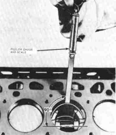 This is Ford's recommended way of measuring piston-to-bore clearance. The
bore is lubricated with oil, the piston and feeler gauge inserted, and a
special scale (a fish scale, except with a clamp to attach it to the feeler)
is used to measure the drag as the gauge is pulled out.
This is Ford's recommended way of measuring piston-to-bore clearance. The
bore is lubricated with oil, the piston and feeler gauge inserted, and a
special scale (a fish scale, except with a clamp to attach it to the feeler)
is used to measure the drag as the gauge is pulled out.
Under controlled conditions, with a known cylinder finish and specific
lubricant, the feeler drag method can be very accurate. Under uncontrolled
conditions with an inexperienced mechanic it's still accurate enough to
measure within half a thousandth.
Ford specifies a *run-in* bore, that is, one from a used engine that has worn
all the sharp honing peaks off. Using plain 30-weight oil, use a feeler gauge
1.2 inch wide, 6 inches long, and .0035" thick. Put the feeler perpendicular
to the piston pin and parallel with the bore axis, and pull the feeler out
with a slow, smooth stroke while watching the spring scale. It may take
several tries to get a repeatable reading.
Ford's chart specifies:
Pull    Clearance
12 lb.  .0014 in.
10 lb.  .0018 in.
 8 lb.  .0023 in.
 7 lb.  .0025 in.
 6 lb.  .0027 in.
 5 lb.  .0030 in.
 4 lb.  .0032 in.
 3 lb.  .0033 in.
 2 lb.  .0036 in.
 1 lb.  .0038 in.
Note you can actually measure clearances larger than the thickness of the
feeler; this is an effect of the viscosity of the lubricant.
 These nifty little brackets were for servicing FE heads. Back in the old days
valve jobs at 20,000 mile intervals weren't uncommon, so tools like this were
handy for holding the head securely while chiseling carbon, grinding seats,
etc.
These nifty little brackets were for servicing FE heads. Back in the old days
valve jobs at 20,000 mile intervals weren't uncommon, so tools like this were
handy for holding the head securely while chiseling carbon, grinding seats,
etc.
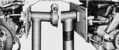
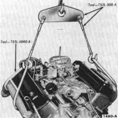 This set of brackets was to be used to lifting the Y-Block engines. Ford
didn't want people using any old bolt holes to lift it.
This set of brackets was to be used to lifting the Y-Block engines. Ford
didn't want people using any old bolt holes to lift it.
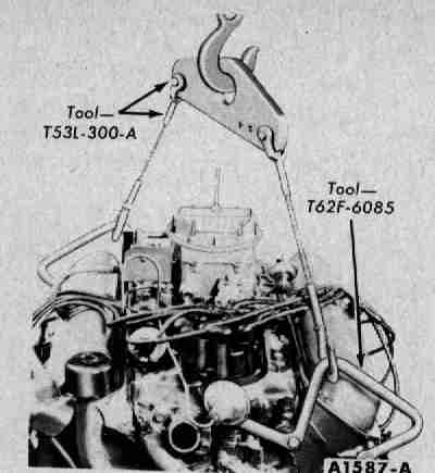 This set of brackets was to be used to lifting the early Windsor engines.
 Ford had a custom bracket for everything. This one grabs under the small
six's manifolds to lift it out of the engine compartment.
Ford had a custom bracket for everything. This one grabs under the small
six's manifolds to lift it out of the engine compartment.
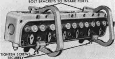 Head removal and holding tools for 223 Six. A convenient set of handles for
lifting the head off or back on the engine, and fixtures for holding the head
for service.
Head removal and holding tools for 223 Six. A convenient set of handles for
lifting the head off or back on the engine, and fixtures for holding the head
for service.
 Ford engine stands always grab the engine from the side and use a worm gear
setup to rotate the engine end-for-end. They've done this ever since the days
of the flatheads. I've never seen one for sale, but I bet this official Ford
tool costs as much as a rebuilt engine...
Ford engine stands always grab the engine from the side and use a worm gear
setup to rotate the engine end-for-end. They've done this ever since the days
of the flatheads. I've never seen one for sale, but I bet this official Ford
tool costs as much as a rebuilt engine...
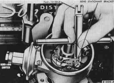 When setting points on a Ford, you were supposed to bend the point arm with
this special Ford tool instead of loosening the screw. I bet you didn't know
that.
When setting points on a Ford, you were supposed to bend the point arm with
this special Ford tool instead of loosening the screw. I bet you didn't know
that.
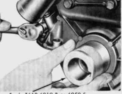
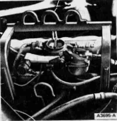
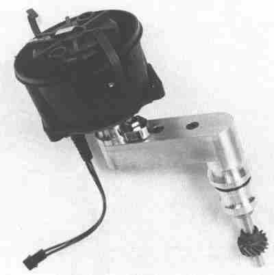 Kuntz and Craft of Arkadelphia, Arkansas used to make these nifty little
gimmers circa 1993. They had them for the 429/460, Cleveland, Windsor, and FE
engines. Just the trick to clear a blower snout or a trick independent runner
induction system.
Kuntz and Craft of Arkadelphia, Arkansas used to make these nifty little
gimmers circa 1993. They had them for the 429/460, Cleveland, Windsor, and FE
engines. Just the trick to clear a blower snout or a trick independent runner
induction system.
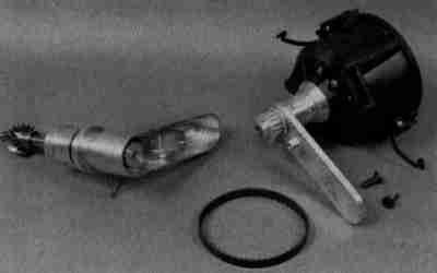 Here's a shot of the inside of the offset housing. Small timing belt is all
you need to turn the rotor.
Here's a shot of the inside of the offset housing. Small timing belt is all
you need to turn the rotor.
 This adapter plate was available from McLeod in 1985. It lets you put a T5 up
against a TopLoader bellhousing.
This adapter plate was available from McLeod in 1985. It lets you put a T5 up
against a TopLoader bellhousing.
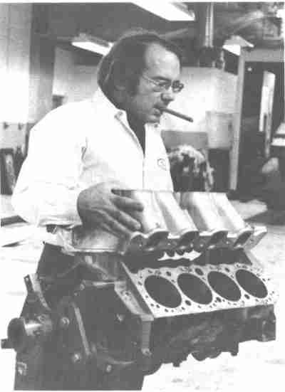 This interesting image appears on the flyleaf of "The Chevrolet Racing Engine"
by Grumpy Jenkins. That's a Chevy block. And that's a Weiand tunnel ram for
a 351 Cleveland. Hmm...
This interesting image appears on the flyleaf of "The Chevrolet Racing Engine"
by Grumpy Jenkins. That's a Chevy block. And that's a Weiand tunnel ram for
a 351 Cleveland. Hmm...
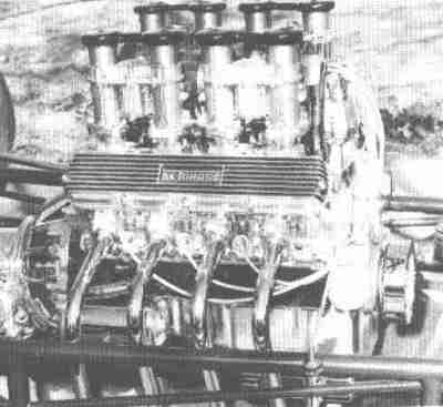 These ultra-rare Weslake heads were intended for the DeTomaso Mangusta. None
made it into Mangustas from the factory; this pair is on a 289 or 302 in a
street rod. The very small header tubes were probably the work the the car
builder.
These ultra-rare Weslake heads were intended for the DeTomaso Mangusta. None
made it into Mangustas from the factory; this pair is on a 289 or 302 in a
street rod. The very small header tubes were probably the work the the car
builder.
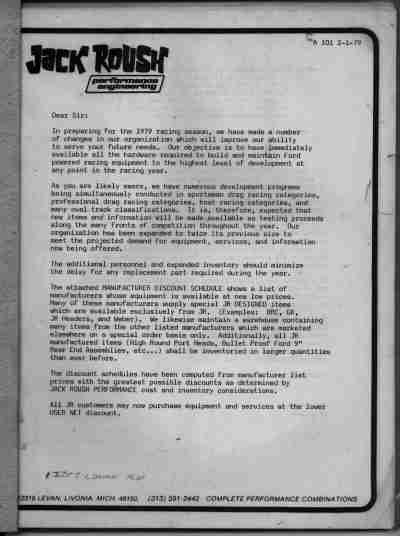 How about a 1979 Roush catalog? Just after his breakup with Wayne Gapp, many
part numbers still start with "GRxx".
How about a 1979 Roush catalog? Just after his breakup with Wayne Gapp, many
part numbers still start with "GRxx".