brought to you by: Dave Williams
This page: www.bacomatic.org/~dw/fordv8/windsor/windsor.htm
Main page:
http://www.bacomatic.org/~dw/index.htm
Last Updated: 18 Sep 2003
Author: Dave Williams; dlwilliams=aristotle=net
displacement    221     255     260     289     302     351W
years made

bore                                    4.0"    4.0"    4.0"
stroke                                  2.87"   3.0"    3.5"
deck height     8.206"  8.206"  8.206"  8.206"  8.206"  9.50"
rod length      5.15"   5.15"   5.15"   5.15"   5.09"   5.956"
pin height
pin diameter    .912"   .912"   .912"   .912"   .912"   .912"
pin offset                                      .0625"  .0625"


length
width
height
weight         460 (221-302), 500 (BOSS 302), 525 (351W) [Peterson Pub.]


bore spacing
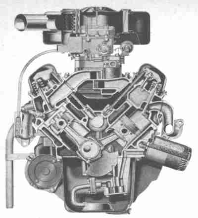 221 Fairlane engine. Note generous water jacketing, road draft tube.
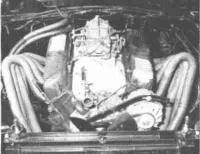
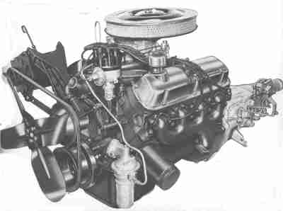 This 1964 image is a 260 from a Fairlane. Note the stout generator bracket,
aluminum water pump, spin-on fuel filter, and the unusual inward tilt of the
driver's side exhaust manifold. That's a Borg/Warner T-10 four speed in back.
The carburetor under the jaunty open-element air filter is an ordinary
Autolite two barrel.
This 1964 image is a 260 from a Fairlane. Note the stout generator bracket,
aluminum water pump, spin-on fuel filter, and the unusual inward tilt of the
driver's side exhaust manifold. That's a Borg/Warner T-10 four speed in back.
The carburetor under the jaunty open-element air filter is an ordinary
Autolite two barrel.
"Complete Book Of Engines No. 2" from 1966
"289 C.I.D. Mustang Competition Engine Specifications"
Piston to bore .......................................... .0042 - .0048
Top of block to piston .................................. .015 - .018
Connecting rod, vertical clearance ...................... .0015 - .003
Side clearance, total 2 rods ............................ .014 - .024
Main bearings vertical clearance ........................ .0022 - .0025
End clearance ........................................... .006 - .008
Head volume C.C.'s ...................................... 44-48
Compression ratio ....................................... 10.5 - 10.8:1
  Carburetor .......................................... Holley No. 2668
  Primary Venturi .............................................. 1 5/16
  Secondary Venturi ............................................. 1 3/8
  Throttle Bore ............................................... 1 11/16
  Nominal Flow @ 1 1/2-in. hg. ................................ 715 CFM
  Primary Jets ................................................. #67-70
  Secondary Jets ............................................... #78-82
Note: High numbered jets are high flow, low numbered jets are low flow.
Valve spring pressures -- 110 lbs. - 120 lbs. @ 1.770"
Valve clearance -- int. .018 ex. .020 (hot)
Spark plugs ......................... Autolite BTF1, BF603, BF601, BF12
Ignition timing ................. 10 - 12 deg initial 36 - 38 deg total
Point clearance ........................................... .016 - .018
Dwell ..................................... 25 deg /point, 33 deg total
Recommended oil ................ S.A.E. 40W non-detergent, Castrol R-40
"Complete Book Of Engines No. 2" from 1966
"289 C.I.D. Cobra Competition Engine Specifications"
Piston to bore .......................................... .0042 - .0048
Top of block to piston .................................. .015 - .018
Connecting rod, vertical clearance ...................... .0015 - .003
Side clearance, total 2 rods ............................ .014 - .024
Main bearings vertical clearance ........................ .0022 - .0025
End clearance ........................................... .006 - .008
Valve lift ...................................................... .500"
Valve timing ................................ Int. Op. .... 37 deg BTDC
                                              Int. Cl ..... 72 deg ABDC
                                              Exh. Op ..... 76 deg BBDC
                                              Exh. Cl ..... 32 deg ATDC
                                                        50 - 60
Above checked at .025 clearance Int. @ Exh, @ .001 valve lift
Head colume in C.C.'s ........................................... 44-48
Compression ratio ....................................... 10.5 - 10.8:1
Carburetion: 4--48 I.D.A.I. Weber
  Main Jets ................................................. 150 - 170
  Air corr. jets ............................................ 100 - 150
  Emulsion tube .................................................... F7
  Choke size ................................................... 42 mm.
  Float level .................... Top of float 6mm. above bowl surface
                                            with carburetor top removed
  Fuel pressure .......................................... 4 - 5 P.S.I.
Valve settings ............................. Int. .025, Exh. .025 (hot)
Valve spring pressures ..... 110 lbs. - 120 lbs. @ 1.770" loaded height
Spark plugs ............................... Autolite BTF1, BF603, BF601
Ignition timing ................ 10 - 12 deg initial, 36 - 38 deg total
Point clearance ........................................... .016 - .018
Recommended oil ..................... S.A.E. 50W mineral or Castrol R40
"Complete Book Of Engines No. 2" from 1966
                                                      Thread  Installation
Operation                                              Size     Torque
Bolt -- Rocker arm cover to cylinder head ............ 1/4-20    3-5 ft.lbs.
Bolt -- Oil pan ......................................
Bolt -- Pressure plate to flywheel ................... 5/16-18   12-20 ft.lbs.
Bolt -- Cam sprocket to camshaft ..................... 3/8-16    30-35 ft.lbs.
Nut -- Rocker arm adjusting ..........................
Bolt -- Flywheel to crankshaft ....................... 7/16-20   78-85 ft.lbs.
Bolt -- Main bearing cap ............................. 7/16-14   60-70 ft.lbs.
Plug -- Oil pan drain ................................ 1/2-20    15-20 ft.lbs.
Bolt -- Crankshaft damper to crankshaft (hand start
        -- run down with impact wrench ............... 5/8-18    120-140 ft.lbs.
Spark plug ........................................... 18MM      12-25 ft.lbs.
Oil filter cartridge ................ Tighten 1/2 turn after gasket contact
Insert -- Oil filter mounting to block ............... 1-1/16-12 60-100 ft.lbs.
Bolt -- Exhaust manifold to cylinder head ............ 3/8-16    13-18 ft.lbs.
Nut -- Carburetor mounting ........................... 5/16-24   12-15 ft.lbs.
Bolt -- Distributor hold down ........................ 5/16-18   12-15 ft.lbs.
Bolt -- Generator bracket to cyl. head ............... 3/8-16    30-35 ft.lbs.
Bolt -- Front cover .................................. 5/16-18   12-15 ft.lbs.
Bolt -- Oil filler tube bracket to generator bracket
        (hand start and run-down with impact wrench) . 1/4-20    6-9 ft.lbs.
Nut -- Connecting rod
Hand torque 40-45 lbs. ............................... 3/8-24    40-45 ft.lbs.ref.
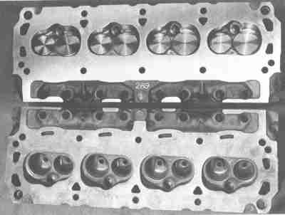
 Shelby 289 exhaust ports. Note how the port roof has been raused as much as
possible.
Shelby 289 exhaust ports. Note how the port roof has been raused as much as
possible.
 Shelby 289 head after plunge cutting to unshroud the valves. The plug side of
the wall was usually laid back a bit further before the heads were sent off to
have the coolant passages welded up.
Shelby 289 head after plunge cutting to unshroud the valves. The plug side of
the wall was usually laid back a bit further before the heads were sent off to
have the coolant passages welded up.
 Shelby 289 cooling passage mod. Shelby's engine builders welded up the
coolant passage in an effort to reinforce the deck and reduce the chance of
blowing head gaskets.
Shelby 289 cooling passage mod. Shelby's engine builders welded up the
coolant passage in an effort to reinforce the deck and reduce the chance of
blowing head gaskets.
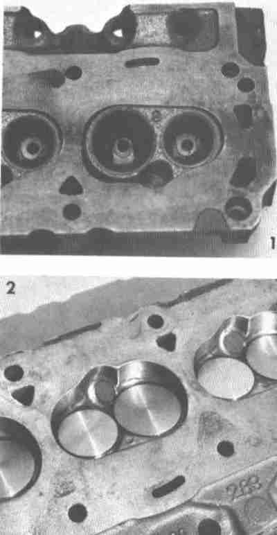
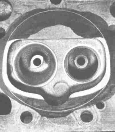
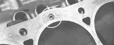
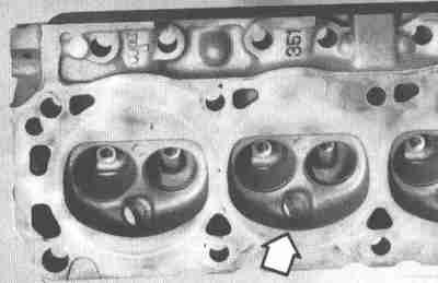 The C9OE or D0OE heads are useful for 289s, 302s, and small strokers,
depending on how much you want to put into porting. These heads are directly
interchangeable and identical other than the casting numbers; it's not
uncommon to find one of each on an all-original 351. Arrow points to
crescent-shaped quench area on plug side outlined by the gasket imprint.
The C9OE or D0OE heads are useful for 289s, 302s, and small strokers,
depending on how much you want to put into porting. These heads are directly
interchangeable and identical other than the casting numbers; it's not
uncommon to find one of each on an all-original 351. Arrow points to
crescent-shaped quench area on plug side outlined by the gasket imprint.
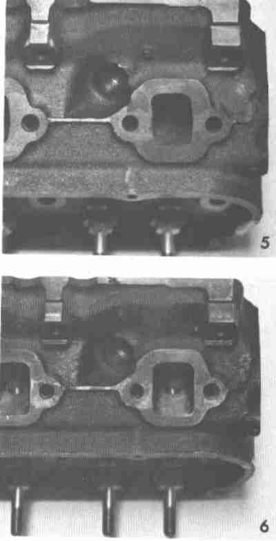
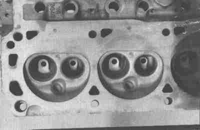 This is the D7OE large-chamber 351W head. The D7OE heads are useful for
larger strokers. It's hard to get compression *out* of a 377 or larger
Windsor! The ports and valves are identical to the C9 and D0 heads. Note the
lack of the outboard quench area compared to the early heads.
This is the D7OE large-chamber 351W head. The D7OE heads are useful for
larger strokers. It's hard to get compression *out* of a 377 or larger
Windsor! The ports and valves are identical to the C9 and D0 heads. Note the
lack of the outboard quench area compared to the early heads.
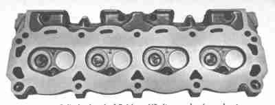 260 cylinder head. Note small valves, very tight chamber. A pair of these
will raise the compression ratio of a 302 or 5.0 right on up there, but the
ports and valves are proportionally smaller, so there'd be no real gain from
doing so.
260 cylinder head. Note small valves, very tight chamber. A pair of these
will raise the compression ratio of a 302 or 5.0 right on up there, but the
ports and valves are proportionally smaller, so there'd be no real gain from
doing so.
 This is the 289 4V small combustion chamber, which is characterized by the
outboard chamber walls being pulled in and leaving the plug in a pocket. A
handful of early 302 4V also got these heads. A common casting number is
C6AE. These work nicely on 302 and 5.0 engines, usually worth a full ratio of
increased compression.
This is the 289 4V small combustion chamber, which is characterized by the
outboard chamber walls being pulled in and leaving the plug in a pocket. A
handful of early 302 4V also got these heads. A common casting number is
C6AE. These work nicely on 302 and 5.0 engines, usually worth a full ratio of
increased compression.
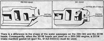 This image from Ford shows the difference in the intake water ports between
the small Windsors and the early 351s. The pictures are upside down for some
reason. Ford itself is the origin of the claim that ordinary 302 gaskets
won't seal with Windsor heads. In actuality they work just fine; the extra
intake bolt holes are blind and no water can leak through.
This image from Ford shows the difference in the intake water ports between
the small Windsors and the early 351s. The pictures are upside down for some
reason. Ford itself is the origin of the claim that ordinary 302 gaskets
won't seal with Windsor heads. In actuality they work just fine; the extra
intake bolt holes are blind and no water can leak through.
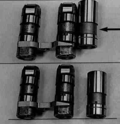 This shows the difference in length between the hydraulic roller and flat
tappets. The lifter bores in the block are the same length, but slightly
raised on the roller blocks.
This shows the difference in length between the hydraulic roller and flat
tappets. The lifter bores in the block are the same length, but slightly
raised on the roller blocks.
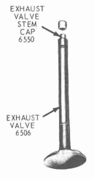 Some '70s 302s came with this type of exhaust valve. The tips are reduced in
diameter and they use hard steel lash caps. Ford had more valve stem and
pushrod lengths than you could shake a stick at, too - most of them so close
only the calipers can tell you for sure.
Some '70s 302s came with this type of exhaust valve. The tips are reduced in
diameter and they use hard steel lash caps. Ford had more valve stem and
pushrod lengths than you could shake a stick at, too - most of them so close
only the calipers can tell you for sure.
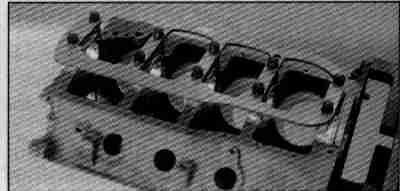
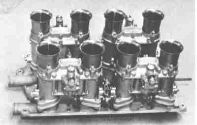 Shelby American intake with Weber carburetors. Webers were the induction
setup of choice where rules permitted.
Shelby American intake with Weber carburetors. Webers were the induction
setup of choice where rules permitted.
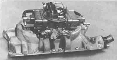 Shelby American intake and 715 CFM center-pivot Holley. This is for a GT350R
competition model. The dual plane intake helped spread out the torque curve
of the high-winding 289 engines.
Shelby American intake and 715 CFM center-pivot Holley. This is for a GT350R
competition model. The dual plane intake helped spread out the torque curve
of the high-winding 289 engines.
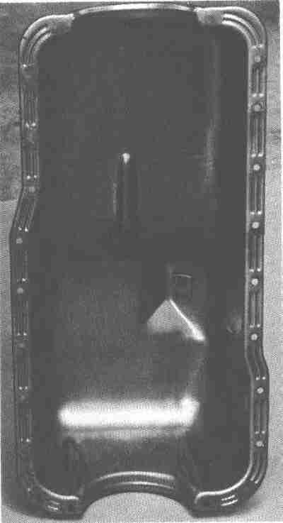 Stock 289 oil pan was an unadorned stamping, nothing to brag about. The small
block Ford was quite wide across the pan rails and the pan was relatively
deep, so the stock Ford pans actually worked better than baffled pans on, say,
Brand C engines.
Stock 289 oil pan was an unadorned stamping, nothing to brag about. The small
block Ford was quite wide across the pan rails and the pan was relatively
deep, so the stock Ford pans actually worked better than baffled pans on, say,
Brand C engines.
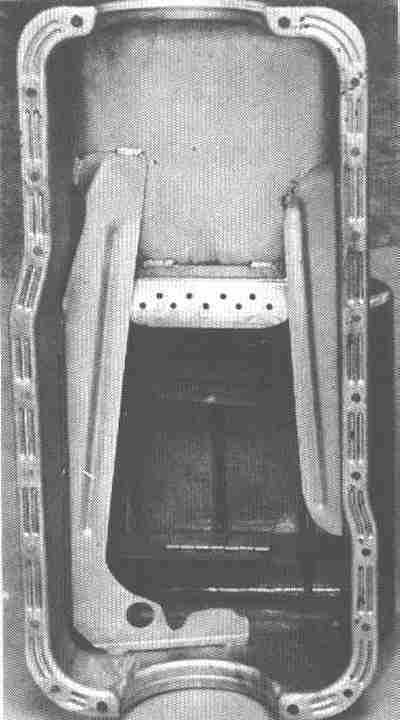 Competition Cobra pan with internal baffles. This part was also available
from Ford's parts department.
Competition Cobra pan with internal baffles. This part was also available
from Ford's parts department.
 Shelby cast aluminum oil pan on Mustang Cobra. The cast pans weren't as light
as the fabricated steel pans on the early AC Cobras, but they were cheaper and
they looked great.
Shelby cast aluminum oil pan on Mustang Cobra. The cast pans weren't as light
as the fabricated steel pans on the early AC Cobras, but they were cheaper and
they looked great.
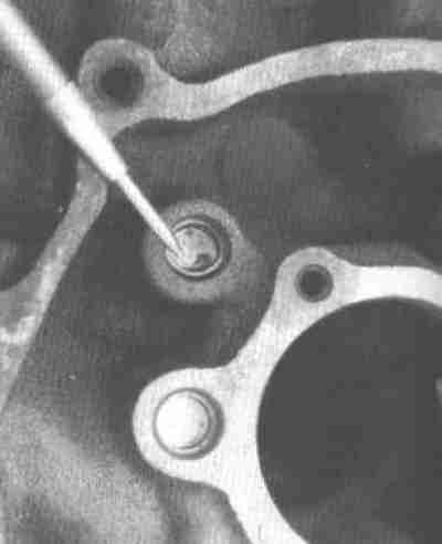 221-302 and 5.0 engines usually have pressed-in cup plugs sealing the oil
galleries. 351W engines sometimes have screw-in plugs. Though the cup plugs
seem to be reliable enough in service, most racers drill and tap the block for
1/4 NPT pipe plugs. The plug below the one indicated with the pick is the
main oil gallery. Some cam retainer plates cover this plug to ensure it can't
come out.
221-302 and 5.0 engines usually have pressed-in cup plugs sealing the oil
galleries. 351W engines sometimes have screw-in plugs. Though the cup plugs
seem to be reliable enough in service, most racers drill and tap the block for
1/4 NPT pipe plugs. The plug below the one indicated with the pick is the
main oil gallery. Some cam retainer plates cover this plug to ensure it can't
come out.
 Racing modification feeds return oil from oil cooler or dry sump to both ends
of the main oil gallery to equalize pressure throughout the system.
Racing modification feeds return oil from oil cooler or dry sump to both ends
of the main oil gallery to equalize pressure throughout the system.
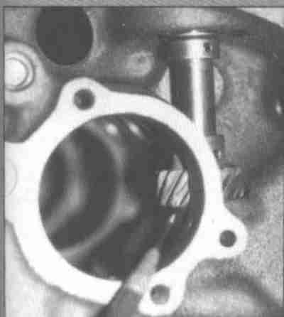 The small block Fords (both Windsor and Cleveland) pull the cam gear down
against the block, as opposed to pushing it up against the distributor housing
like a small block Chevy. If you insert the distributor and move the shaft up
and down, clearance should be on the order of .020". Adjusting the clearance
requires driving out the roll pin, moving the gear to the correct position,
and drilling a new hole through the distributor shaft.
The small block Fords (both Windsor and Cleveland) pull the cam gear down
against the block, as opposed to pushing it up against the distributor housing
like a small block Chevy. If you insert the distributor and move the shaft up
and down, clearance should be on the order of .020". Adjusting the clearance
requires driving out the roll pin, moving the gear to the correct position,
and drilling a new hole through the distributor shaft.
If the wear surface on the block has been damaged you'd normally throw the block away. If it's a rare or expensive block you can re-cut the surface by making an arbor to hold a valve spring seat cutter of the correct size. Then you can use a Chevy distributor shim as a spacer. You'll have to open the ID of the shim up slightly to fit the Ford shaft.
The small hole to the right of the pencil is an oil passage leading to the lower distributor shaft. Early Windsors used a groove in the cam retainer plate that led drain oil from the front cam bearing down to the oilway. Later engines use a cam bearing with a short groove leading to a second drilling that intersects this one, or (in a Cleveland) the drilling is angled.
The distributor gear is lubed by oil slung off the #1 crank throw and by oil
drainback from the left front head, just outside the picture to the right.
Some racers drill a small hole in the driver's side lifter gallery plug which
shoots some oil in the general vicinity, but it would normally go right past
the side of the distributor shaft and onto the timing chain.
 Roller cam 5.0s have a longer shaft than the earlier engines. The early shaft
is long enough to go completely through the block; Ford apparently lengthened
the shaft to get a longer hex inside to hold the oil pump drive rod. Wear in
the hex was a common problem in older engines. However, if you want to use a
large diameter oil pump drive shaft you will have to shorten the shaft. You
can do it with a hacksaw if you have to; it doesn't have to be super-precise,
just short enough to clear the shoulder on the big shaft.
Roller cam 5.0s have a longer shaft than the earlier engines. The early shaft
is long enough to go completely through the block; Ford apparently lengthened
the shaft to get a longer hex inside to hold the oil pump drive rod. Wear in
the hex was a common problem in older engines. However, if you want to use a
large diameter oil pump drive shaft you will have to shorten the shaft. You
can do it with a hacksaw if you have to; it doesn't have to be super-precise,
just short enough to clear the shoulder on the big shaft.
 This wintage tray is made by MPG Head Service in Colorado. It's available
from them, various vendors, and through Ford Motorsport with a Ford part
number. I've used one of these before. It's a pretty decent piece, sort of a
combination scraper/tray. It's adjustable left to right to set the scraper as
close as possible to the crank. The one I used fit fine on a 375 Windsor
stroker. MPG also makes them for the 302.
This wintage tray is made by MPG Head Service in Colorado. It's available
from them, various vendors, and through Ford Motorsport with a Ford part
number. I've used one of these before. It's a pretty decent piece, sort of a
combination scraper/tray. It's adjustable left to right to set the scraper as
close as possible to the crank. The one I used fit fine on a 375 Windsor
stroker. MPG also makes them for the 302.
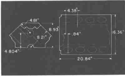 Basic block dimensions for the 221-302 Windsors. Small isn't it? The 4.804"
cam-to-crank centerline dimension is the same on the 351W, which can accept
strokes out to 4.2".
Basic block dimensions for the 221-302 Windsors. Small isn't it? The 4.804"
cam-to-crank centerline dimension is the same on the 351W, which can accept
strokes out to 4.2".
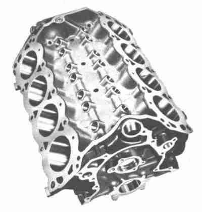
 This 1968 promotional image is apparently the source of the persistent idea
that 302 blocks have deeper cylinder bores than 289 blocks. In fact, all 260-
289-302 and 5.0 bores measure out at 5-1/8". Such mismatches between iron and
documentation aren't all that unusual; the docs have to be written before the
design is finalized, and sometimes production changes creep in.
This 1968 promotional image is apparently the source of the persistent idea
that 302 blocks have deeper cylinder bores than 289 blocks. In fact, all 260-
289-302 and 5.0 bores measure out at 5-1/8". Such mismatches between iron and
documentation aren't all that unusual; the docs have to be written before the
design is finalized, and sometimes production changes creep in.
 This is a '66 Shelby 289 block with the top water hole blocked off. It was
part of Shelby's modifications to the 289 HiPo; they claimed it improved the
cooling by rerouting part of the flow. Oddly enough, the holes not only came
and went at various times during 289/302/5.0 production, but they also moved
from the center to the side... and the various heads varied similarly!
This is a '66 Shelby 289 block with the top water hole blocked off. It was
part of Shelby's modifications to the 289 HiPo; they claimed it improved the
cooling by rerouting part of the flow. Oddly enough, the holes not only came
and went at various times during 289/302/5.0 production, but they also moved
from the center to the side... and the various heads varied similarly!
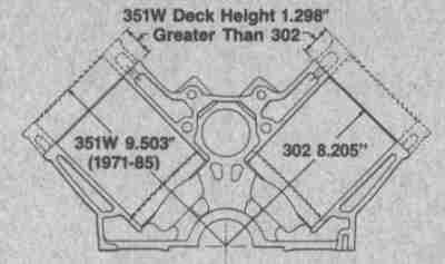 The model years stop at 1985 because this is a very old drawing. The 351W
is about 1.3 inches taller than the 302. By comparison to other American V8s,
the 302 is the shortest-deck American V8 ever produced. The 351W looks
enormous by comparison, but at 9.5 inches it's only average.
The model years stop at 1985 because this is a very old drawing. The 351W
is about 1.3 inches taller than the 302. By comparison to other American V8s,
the 302 is the shortest-deck American V8 ever produced. The 351W looks
enormous by comparison, but at 9.5 inches it's only average.
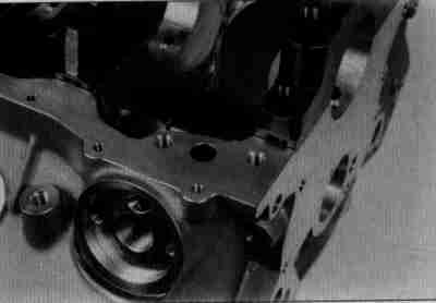
 This is a 221 block. Note the mystery boss at the right rear.
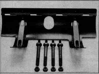
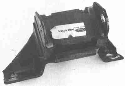 This is the yoke style motor mount you'll find on '60s and '70s Fords. Some
later cars wrapped a metal housing all the way around the rubber to keep the
engine from flopping around if the rubber separated, which was a fairly common
failure mode. Since the lower half of the mount could pivot around the frame
bracket bolt the rubber was sometimes loaded in shear instead of plain tension
and compression. Trucks usually used a stud and plate instead of a yoke.
This is the yoke style motor mount you'll find on '60s and '70s Fords. Some
later cars wrapped a metal housing all the way around the rubber to keep the
engine from flopping around if the rubber separated, which was a fairly common
failure mode. Since the lower half of the mount could pivot around the frame
bracket bolt the rubber was sometimes loaded in shear instead of plain tension
and compression. Trucks usually used a stud and plate instead of a yoke.
A few applications used a sheet metal shield with an asbestos liner to keep
the exhaust manifolds from cooking the rubber. I always used to throw them
away; now that I know better I grab them whenever I can find them.
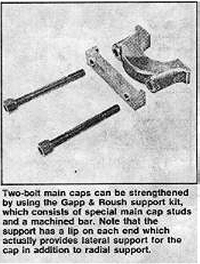 Gapp & Roush used to recommend and sell these main cap support straps. They
were once popular for all engines, not just Fords. Apparently they've gone
out of fashion now.
Gapp & Roush used to recommend and sell these main cap support straps. They
were once popular for all engines, not just Fords. Apparently they've gone
out of fashion now.
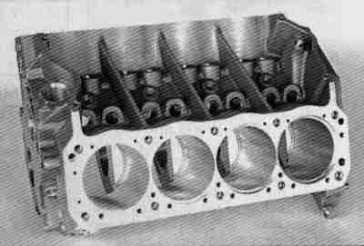
 Really lousy image of a Ford Motorsport A4 block, part number M-6010-A4. They
come .017 undersize so you can finish the bores the way you want. Trendy
splayed-bolt main caps are only used on the middle three positions. #1 and #5
not only aren't four bolt, they're plain old 302 caps, not even HP289 or
Mexican 302 style. There is more meat in the cylinder walls, main webs, and
it's filled in along the pan rail. Various sources report the A4 is about 40
pounds heavier than a standard 302 block; that'd make it right around 175
pounds - the same weight as a standard 351C, 351W, or 390 FE (yes!) block.
Frankly, unless you're determined to build an 8.2" deck height 302, you'd
probably be better off starting with a 351.
Really lousy image of a Ford Motorsport A4 block, part number M-6010-A4. They
come .017 undersize so you can finish the bores the way you want. Trendy
splayed-bolt main caps are only used on the middle three positions. #1 and #5
not only aren't four bolt, they're plain old 302 caps, not even HP289 or
Mexican 302 style. There is more meat in the cylinder walls, main webs, and
it's filled in along the pan rail. Various sources report the A4 is about 40
pounds heavier than a standard 302 block; that'd make it right around 175
pounds - the same weight as a standard 351C, 351W, or 390 FE (yes!) block.
Frankly, unless you're determined to build an 8.2" deck height 302, you'd
probably be better off starting with a 351.
 Fontana aluminum "Clevor" block. I hate the word; it sounds like the name of
some hillbilly with overalls and no teeth. Fontana has made these for almost
20 years in various configurations. If you find a used one, double check the
main bearing size and deck height, and you'll need the special Fontana timing
chain cover. If you want a new one they're still available. Price? "If you
have to ask, you probably can't afford it," as JP Morgan reputedly said.
Fontana aluminum "Clevor" block. I hate the word; it sounds like the name of
some hillbilly with overalls and no teeth. Fontana has made these for almost
20 years in various configurations. If you find a used one, double check the
main bearing size and deck height, and you'll need the special Fontana timing
chain cover. If you want a new one they're still available. Price? "If you
have to ask, you probably can't afford it," as JP Morgan reputedly said.
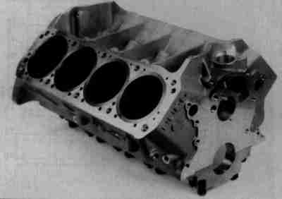 Ah, a better shot of a Fontana block. This one takes a Cleveland cam and
crank.
Ah, a better shot of a Fontana block. This one takes a Cleveland cam and
crank.
 To take the Cleveland cam you need to offset the oil pump .150" outboard. And
you might as well make the pan rails Cleveland-style... the Fontana is really
more of a Cleveland than a Windsor. Four bolt mains on all five caps.
To take the Cleveland cam you need to offset the oil pump .150" outboard. And
you might as well make the pan rails Cleveland-style... the Fontana is really
more of a Cleveland than a Windsor. Four bolt mains on all five caps.
 Nowak stud girdle. This is fairly representative of the 'thin' type girdles
from several manufacturers. Most of them bolt on with no machine work. They
can't hurt, but I don't feel the Windsors have a main cap problem to start
with. By the time you rattle the caps with a blower or nitrous, you're out of
stock block territory anyway.
Nowak stud girdle. This is fairly representative of the 'thin' type girdles
from several manufacturers. Most of them bolt on with no machine work. They
can't hurt, but I don't feel the Windsors have a main cap problem to start
with. By the time you rattle the caps with a blower or nitrous, you're out of
stock block territory anyway.
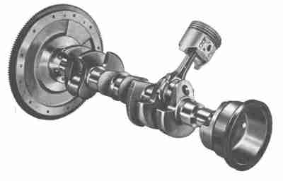 This is a Ford airbrush drawing of a generic Windsor rotating assembly, circa
1964. It has a 289 HiPo harmonic balancer but no add-on bob weight. The
flywheel and balancer clearly show the additional 28.2 oz of weight added to
balance the engine. The weight is not split evenly on the ends; more is on
the front than the back, about 70/30. A 5.0 with the 50oz flywheel has a
weight almost twice as wide, and the harmonic balancer counterweight covers
fully half its diameter instead of being a simple wedge.
This is a Ford airbrush drawing of a generic Windsor rotating assembly, circa
1964. It has a 289 HiPo harmonic balancer but no add-on bob weight. The
flywheel and balancer clearly show the additional 28.2 oz of weight added to
balance the engine. The weight is not split evenly on the ends; more is on
the front than the back, about 70/30. A 5.0 with the 50oz flywheel has a
weight almost twice as wide, and the harmonic balancer counterweight covers
fully half its diameter instead of being a simple wedge.
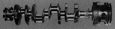
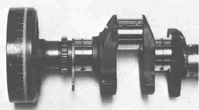 This crank is from a '65 Shelby 289 competition engine. Note the grooved main
journals, 289 HP extra bobweight, and the fully-degreed harmonic balancer.
All these items were available individually from Shelby. Later engines
used grooved bearings instead of grooving the crankshaft.
This crank is from a '65 Shelby 289 competition engine. Note the grooved main
journals, 289 HP extra bobweight, and the fully-degreed harmonic balancer.
All these items were available individually from Shelby. Later engines
used grooved bearings instead of grooving the crankshaft.
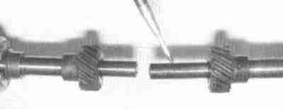
 This shot gives you a good idea of how long the snout is on the small block
crank, and how much leverage the harmonic balancer and pulleys have across the
#1 main. It's not a problem with 289 and 302 cranks, but the lightweight 50-
oz. imbalanced 5.0 cranks break regularly just in front of the first rod throw
when run even for moderate times at high RPM, such as SCCA A-Sedan racing.
This particular crank is from a 1969 DeTomaso Mangusta with a 302.
This shot gives you a good idea of how long the snout is on the small block
crank, and how much leverage the harmonic balancer and pulleys have across the
#1 main. It's not a problem with 289 and 302 cranks, but the lightweight 50-
oz. imbalanced 5.0 cranks break regularly just in front of the first rod throw
when run even for moderate times at high RPM, such as SCCA A-Sedan racing.
This particular crank is from a 1969 DeTomaso Mangusta with a 302.
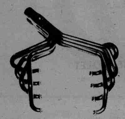
 Wild Herbert & Meek headers for early Pinto swap. They went out of production
around 1980, but they're still the dog's ballocks, eh wot?
Wild Herbert & Meek headers for early Pinto swap. They went out of production
around 1980, but they're still the dog's ballocks, eh wot?
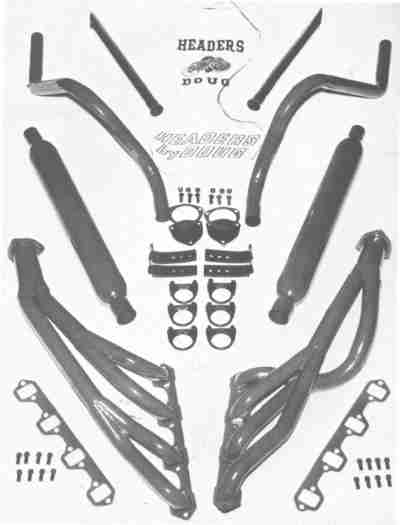 Doug Thorley tri-Y headers for early Mustangs. These are very similar to the
Shelby tri-Ys. You see lots of tri-Y headers on 289 racers. Before exotic
aftermarket heads became available the only practical way to make power was to
stuff as much compression and cam in as you could stand and spin it up just
shy of disintegration. This tended to make the 289s weak in midrange. The
tri-Ys perked up midrange without losing much from the top end.
Doug Thorley tri-Y headers for early Mustangs. These are very similar to the
Shelby tri-Ys. You see lots of tri-Y headers on 289 racers. Before exotic
aftermarket heads became available the only practical way to make power was to
stuff as much compression and cam in as you could stand and spin it up just
shy of disintegration. This tended to make the 289s weak in midrange. The
tri-Ys perked up midrange without losing much from the top end.
 Schoenfeld made these 180 degree headers circa 1983. They cost $159.95 back
then.
Schoenfeld made these 180 degree headers circa 1983. They cost $159.95 back
then.
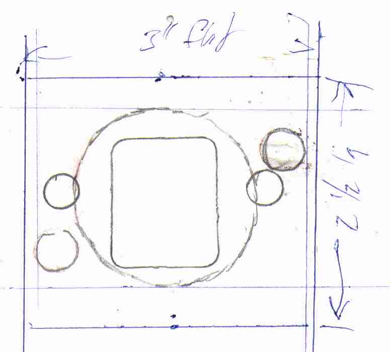 This drawing was made while building a pair of adapters to fit a pair of
Motorsport diagonal-pattern racing headers to a pair of factory 289 heads.
The threads in the diagonal pattern went through the edge of the right hand
countersunk screw.
This drawing was made while building a pair of adapters to fit a pair of
Motorsport diagonal-pattern racing headers to a pair of factory 289 heads.
The threads in the diagonal pattern went through the edge of the right hand
countersunk screw.
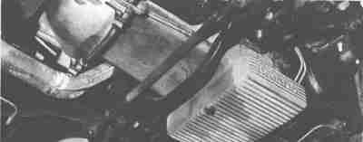
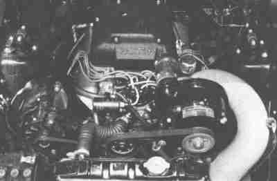 Shelby GT350 with optional Paxton supercharger. Some cars were delivered with
the supercharger as a factory-installed option. Shelby American also marketed
the kits directly and through some Ford dealerships.
Shelby GT350 with optional Paxton supercharger. Some cars were delivered with
the supercharger as a factory-installed option. Shelby American also marketed
the kits directly and through some Ford dealerships.