brought to you by: Dave Williams
This page: www.bacomatic.org/~dw/lt1/lt1.htm
Main page:
http://www.bacomatic.org/~dw/index.htm
Last Updated: 21 Jun 2005
Author: Dave Williams; dlwilliams=aristotle=net
The 229 V6 in my 1980 Malibu station wagon is no powerhouse, but it runs well and is good on gas. However, it has a horrendous rear main seal leak, typical of most Chevy V6s and V8s of the period. Chevy had used a different rubber for the rear main seal, and it hardened and cracked off in chunks, so when you pul out from a stop, oil slops out the back of the pan and all over the exhaust crossover pipe.
I wasn't thrilled about trying to replace the seal from underneath. It's just barely within the bounds of possibility, and the suck factor would be high. An engine R&R, given it's fully loaded with accessories, isn't much more fun. If the 229 has to come out, it sure as heck isn't going to go back in, particularly since the wagon is the new designated trailer-towing vehicle after I sold Thunder.
I bought a wrecked 1995 Camaro with an LT1 in it. It was one of those ideas that looked good at the time. But I hadn't taken the time to do my homework; the LT1 wouldn't accept any of the wagon's accessories. Different power steering pump fittings - not that the hoses would have stretched to the other side, where the LT1 put its pump. Different AC compressor, with alien fittings. The wagon's old A6 system worked fine and had a fresh charge of R12. Even the alternator wiring was different. And the V6's accessories wouldn't bolt to the LT1, because the LT1 had no water pump pulley, and every belt wanted to loop over the water pump.
Being stubborn, I decided to make the LT1 work. I didn't want to completely redo all the accessories and AC, or I would have simply put the Buick Grand National engine in. That's why I didn't put the GN engine in; I thought, "yeah, a Chevy V8, all the V6 stuff will bolt right up." Sometimes I'm a moron.
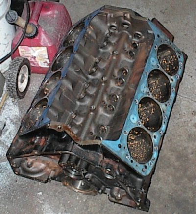
Anyway, the LT1 had been badly damaged in the crash. The block was broken, among other things. So it had to come all the way apart. Putting it back together, things started to get... a little strange.
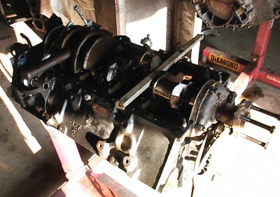 This is the original donor engine being disassembled. The block had been
cracked in the wreck, so it wasn't going to be re-used. Here, I've removed all
the pistons and I'm ready to pull the crank hub. The LT1 doesn't use a
harmonic balancer like a regular small block Chevy. Instead, it has a crank
hub, which simply presses on with no key to align it. The balancer then bolts
to the hub. There are no timing marks on the balancer, since the timing is
set by the position of the Optispark distributor in the timing cover.
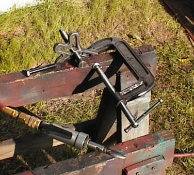 Chevrolet, in their wisdom, went to some very large diameter bolts to hold the
balancer on; larger than anything else in the known universe, which is why my
Lisle balancer puller tool's slots were too small to pass the bolts. So it's
time for some tool modification...
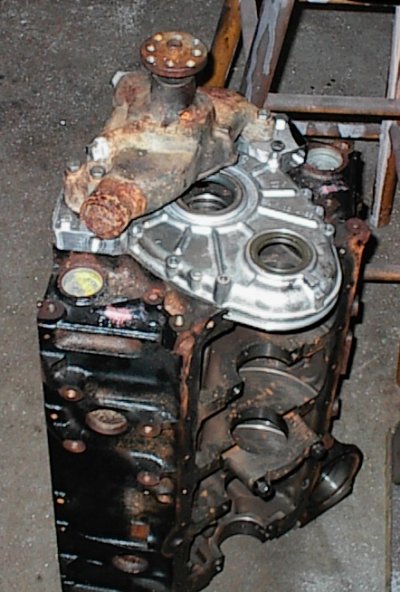
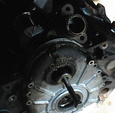 Here's a dim picture of the hub, laying above the timing cover. I nearly
broke the tool before looking in the hub with a flashlight. Instead of being
a straight bore like anything else, there's a web in the hub, with a hole just
large enough to pass the balancer bolt. All I'd been doing was trying to
break the web out. So I screwed a bolt into the end of the crank, through the
hole in the web, to get something to push on.
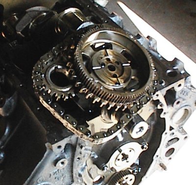 Here's the LT1's timing set. Plain old silent chain, ordinary-looking lower
sprocket, and the special LT1 upper sprocket, with the gear on the back to
drive the water pump idler gear several times crank speed. This is a $150
timing set.
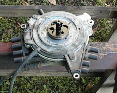 Optispark distributor, back side.
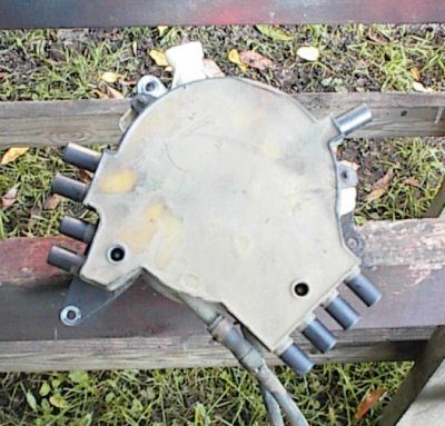 Optispark distributor, front side.
Just the cap costs $100, and you have to pull the harmonic balancer to get to
it. Water pump too, unless you're a contortionist. Ford used the same setup
on their flathead V8s until they upgraded to a distributor on a stick like the
rest of the world. Chevy devolved...
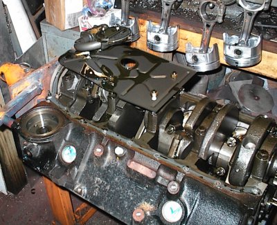 This is a second LT1 I got, as a short block. It came with a milk crate full
of spare rods and pistons, too. This one had two bolt mains. The hole in the
side of the oil pan was a clue there was a problem inside; here, the condition
of the windage tray should peg the clue meter.
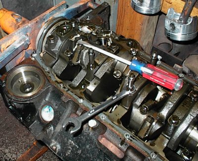 Screwdriver tip points to very short connecting rod. The powder-metal rods in
late models have a tendency to break. Complete disassembly showed it might
not have been the rod's fault this time. The piston pin was broken, one side
still clamped in the pin end, the other in the pan. In the milk crate full of
spares, two other rod/piston pairs had broken pins. The LT1 uses a
lightweight, skirtless piston, and it uses a thinwall wristpin. The pins are
brittle; of 21 rod/piston pairs I checked, three were broken. That's not good
odds.
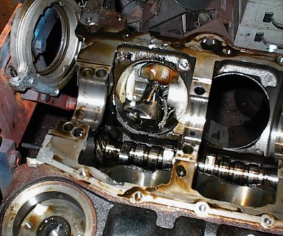 Here's a shot up the bore with the crank out. You can see the left side of
the wristpin is missing.
The crank was undamaged, and I
decided to use it instead of the one out of the first block.
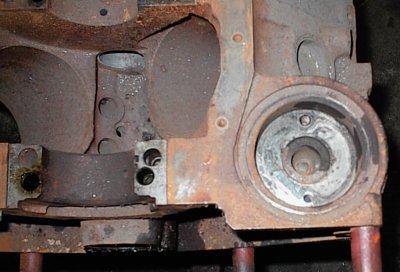 Another friend gave me a third LT1 block. This was another four bolt
main block, and it had an unworn standard bore. Problem was, Arkansas'
infamous humidity had worked on it for a couple of years. It needed a lot of
TLC to get it back into useable shape.
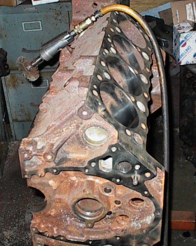 Every lifter bore, every main journal, the main webs, everything, had to be
wire wheeled or sanded. It took a long time.
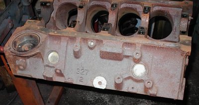 The Mystery Hole. This block had a 1/4 NPT tapped boss that did nothing that
I could figure out. The other two blocks didn't have it. Some later Vortec
V8s and V6s also have mystery holes similar to this one.
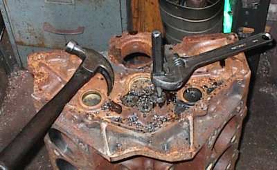 Ah, first you strip the oil plug out with the square bit. Then you drill it
out, drive in the chisel, and turn the mangled remains of the plug out...
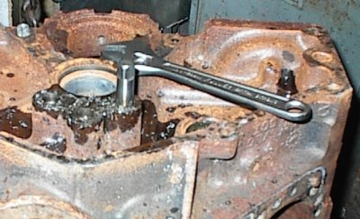 ...then you run a tap in to repair the mangulated threads.
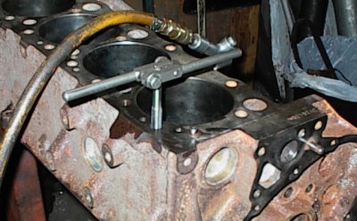 Tapping all the holes to clear the rust and gick out. It's good exercise for
the wrists. At least, that's what I keep telling myself.
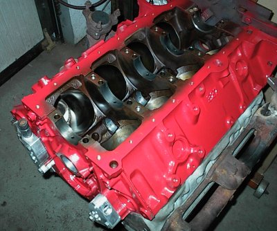 I miked the main bores, miked the crank, popped the bearings and crank in,
tightened the main caps... and the crank wouldn't turn. Vertical clearance
was fine with both the micrometer and Plastigage. I pulled the center three
bearings out, set up a dial indicator, and spun the crank. It was straight.
I laid a straightedge in the main saddles of the block. They were straight.
I finally took a look at the center three main caps... and they were all
shifted visibly to one side. They were 4-bolt caps, but they weren't for that
particular block. The front and rear caps were fine.
At this point, I was out a full day of cleaning, a set of freeze plugs, a can
of paint, a set of cam bearings, and a $80 set of pistons. If I had been
smart, I would have tossed the block and the pistons in the trash, chances of
finding another standard-bore block being remote, and bored the block from the
engine that had tossed a rod; the scratches in the cylinder would have cleaned
up at .030 or .040. Instead, I wound up paying close to $160 to have this
particular block align honed. The shop I farmed it out to honed it a
lot; as in, the timing chain then flapped in the wind when I started
putting it back together again. Fortunately, short timing chains are
available for Chevys that have been align bored or honed. They cost $130. So
I'm out close to $300 because I was too stubborn to write off all the prep
time I'd put in this particular block. This is known as "penny wise and pound
foolish." Or, in practical terms, another yawning hole in my checking account
that I'll have to rationalize as "a learning experience."
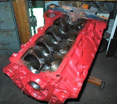 Here we are, back from the other shop, cleaned up, and ready to try again.
Honing oil is full of grit from the stones wearing down, so all the little oil
passages have to be thoroughly cleaned, including flushing around the cam
bearings with solvent and the pressure washer. Yes, I should have knocked the
cam bearings out for cleaning, but it was another case of the stubborns. It
was all sparkly clean behind the bearings from when I had cleaned the block,
so there was no gick back there to hold any grit.
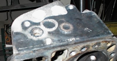 Most Detroit engines sit at a 5 degree or so angle in the chassis, to lower
the transmission and driveshaft. In C4 and later Corvettes, and later
Camaros, the engine sits level. Air bubbles in the older engines would make
their way to the thermostat housing and out, but with the engine sitting
level, that doesn't work so well. The last of the L98s got bleeder ports on
the backs of the heads when in the Corvette and Camaro, and so did the LT1,
even when it was in an Impala. There's a crossover tube at the back with
washers and trapped O-rings, to circulate bubbles and coolant out of the
heads.
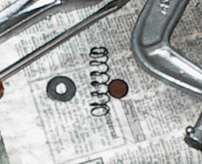 I disassembled and cleaned the oil filter adapter/bypass. The stock bypass is
very weak. I often tap and plug the bypass hole to ensure full flow through
the filter. This time, I found a stiffer spring. It was an adventure getting
the spring and its retaining washer in place, then crimping the edges back
over. All it takes is five hands and the strength of Superman.
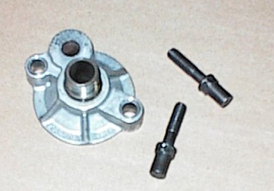 The long, weird bolts clock the oil cooler adapter in relation to the block.
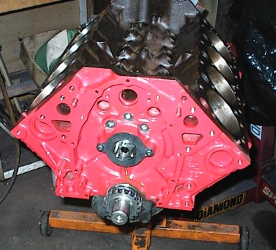 Here the front oil plugs and cam are installed. Some LT1s had .030" holes
drilled in the lifter gallery plugs to purge air and eliminate lifter rattle
if the engine has been sitting a long time. I didn't feel like drilling some
new plugs, so I drove the old ones back in after rodding out the oil passages,
staked the perimeters heavily, and then ran a small bead of epoxy around the
outer edges. I don't think they'll go anywhere.
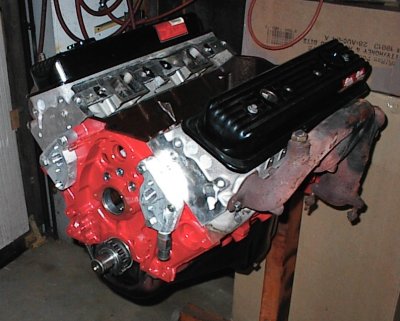 Trial fitting all the bits. The Ford Red paint looks sort of spiffy, doesn't
it?
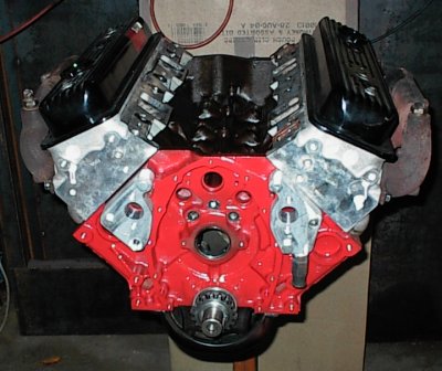 Large hole in the middle was for the ball bearing on the end of the LT1 water
pump drive shaft. It's not used with the new retrofit bits.
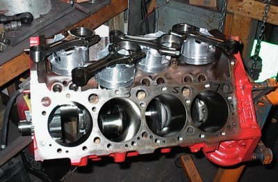 Hanging rods. They're all numbered and dotted to show which way the rods go.
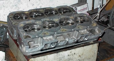 Getting ready for grinding the valve seats. I put a nice three-angle valve
job in, and a set of brand-new Vortec valves and springs. I also ceramic-
coated the valves, which should help reduce any tendency to ping.
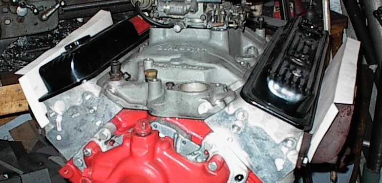
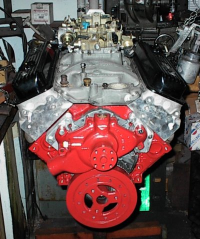 Here we are, another mockup. Heavy L98 350 harmonic balancer, early short
water pump, Offenhauser Dual-Port 360 intake, old Mercury Marine valve covers.
That's an electronic Quadrajet sitting on top.
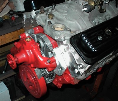 Another angle. Note the timing pointer - the LT1 didn't have one to start
with. The timing cover had to be spotfaced a bit, but the bolt holes lined up
okay.
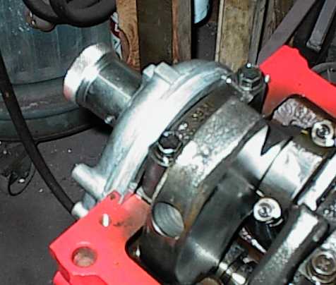 The LT1 timing chain cover has a thick lip. There's only a thin slot for oil
to bleed back between the timing chain and the front main cap. No problem,
though.
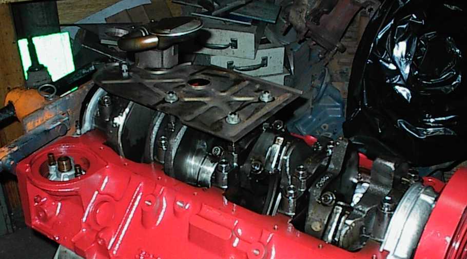 Lots of late Chevy V8s and V6s have this little half-size windage tray. It
covers the sump part of the pan, which is all that is really needed.
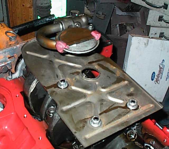 The big hole is for the dipstick. The self-locking nuts are also Loctited.
That's the new-style 3/4" pickup tube, as opposed to the old 5/8" tube. Chevy changed over somewhere in the late '80s. The clay is to verify proper pickup tube height.
Oddly enough, both the the LT1 core motors I got had high volume oil pumps on
them, apparently from the factory.
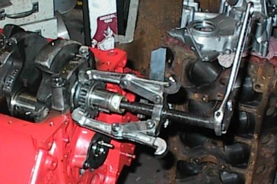 Most people pull the old gear while taking the core engine apart. I leave it
on since it provides a good place to wrap the chain around the nose when you
put the crank in the cleaning tank.
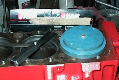 Ring gapping again...
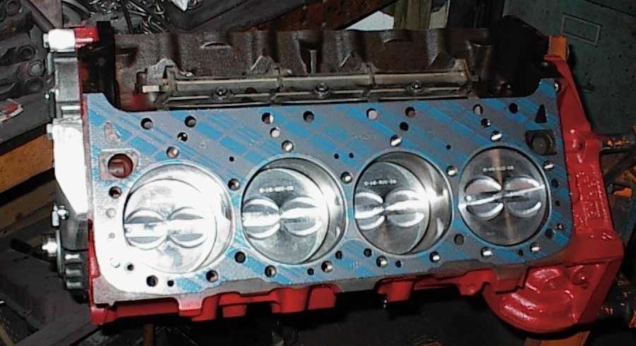 Special LT1 head gaskets were only a couple of dollars more than ordinary
Chevy gaskets. It was nice not to get raped for anything LT1-specific, for a
change.
The first year or two of LT1 head gaskets were extended into the lifter
gallery and had holes for the pushrods. According to lore, the holes were to
hold the pushrods up so they could be installed first, then the head, to speed
assembly. Might even be true... later LT1s got rid of the pushrod holes, but
these Fel-Pro replacement gaskets are the early type.
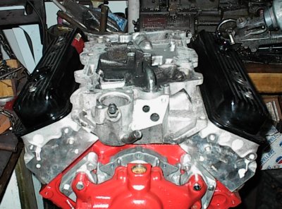 I managed to snag a Vortec lower intake, and thought briefly about using it
instead of the Offy. I didn't feel like redrilling the intake or modifying
the heads again, so I decided to stay with the Offy. Remember both the LT1
and the Vortec use different bolt patterns from each other and either
of the two old-style (original, or 75-degree center bolt) intake
manifold patterns.
Remember, Chevy stuff all interchanges, and they're easy to work on...
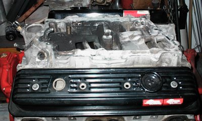 Another view of the Vortec manifold. Some injector bungs, weld up a lid, slap
a throttle body on somewhere, and it'd be a nice setup. It's very similar to
the old CrossFire Injection, except with larger runners.
 Getting ready to transfer-punch the heads for the new intake manifold bolt
holes. First, a pair of old head gaskets so the heads sit at the right
height.
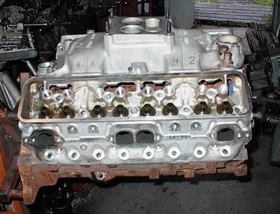 Now everything is mocked up in place.
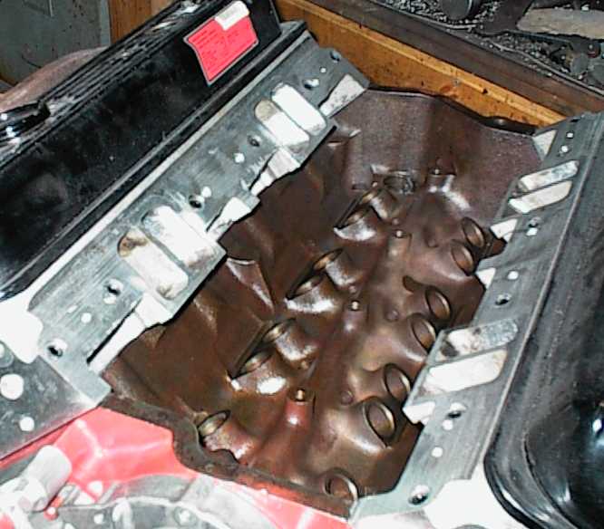 Here are the finished heads. The LT1 holes are plugged with set screws and
silicone sealer; if I ever want to slap an LT1 manifold back on, I can remove
the set screws and do so. The head mating surface on the Offy intake is
skeletonized and the LT1 holes would let stuff fall through into the lifter
galley if they weren't plugged.
A standard 283 water pump almost lines up with the LT1 inlet holes and upper bolt holes. The 229 uses a long pump, so the short 283 pump gives me 1- 1/2" to form adapters.
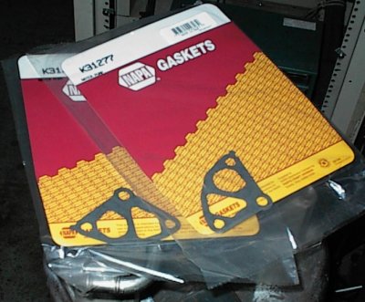 The first thing I did was get some gaskets so I could use them to mark off the
bolt and water holes. This turned out to be a three-day event involving four
parts stores. LT1 gaskets aren't normal stock items. Finally, NAPA came up
with a pair, at $3.50 each. At least $3 of that was probably the big piece of
cardboard and the shrinkwrap! Anything specific to an LT1 is expensive.
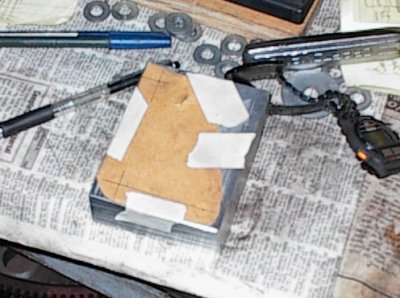 I had some 1-1/8" thick, 3-1/2" wide aluminum bar on hand. Oddball size, but
big enough, anyway. I made a rough template out of file folder stock to get
started.
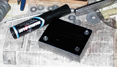 Black it out with ink, transfer the hole locations from the gaskets, drill,
chamfer.
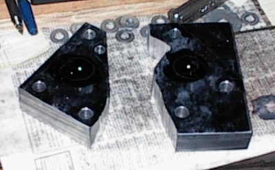 Now we're sawing and grinding. I didn't bother to come up with special
patterns, I just kept whacking at them until they fit.
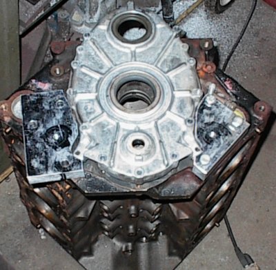 Roughed out with the bandsaw, die grinder, and belt sander. The adapters now
clear the timing cover. All the gasket-spot-transfer-punched mounting holes
wound up aligned okay, much to my surprise...
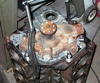 Big C clamp holds water pump in place while I mark where the spots to drill
the pump mounting holes. You can see the extra metal on the driver's side
adapter has been machined off and the corners rounded.
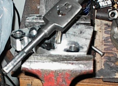 After center punching the hole locations and drilling the mounting holes, I'm
tapping the pump mounting holes.
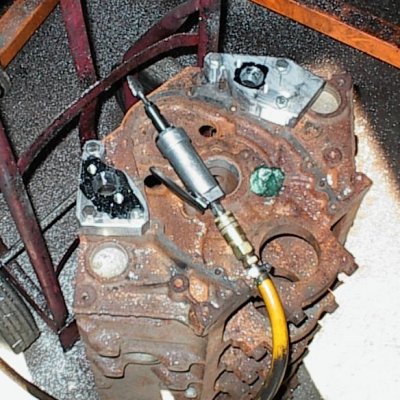 The LT1 water ports in the block were slightly smaller than the 283 pump
outlets. I tapered the holes with the die grinder.
If you look, you'll see I didn't use the LT1's upper pump mounting holes.
They conflicted with the 283 holes. However, the LT1 block has many extra
bosses and tapped holes; two of them were just above the water pump holes.
That's why the adapters reach around the flanges on the timing cover, so they
can grab the top holes.
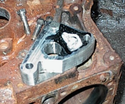 An hour or so with the die grinder hollowed the backs out. It was easier than
setting them up on the milling machine. I left some metal inside to
accomodate the lower water pump bolts. It shouldn't affect flow enough to
worry about.
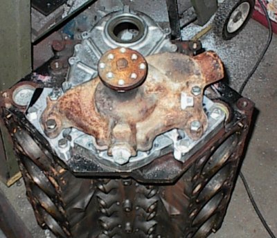 Yes! Finally! The 283 pump is bolted down to the adaptors. There's still
some finish work to do, but they're almost done.
 A view from the bottom.
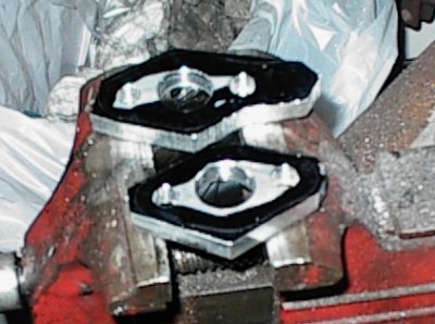 I needed another 3/8" to push the water pump flange out to where it needed to
be. I cut these spacers out of 3/8" plate. Since the bypass hole from the
pump is blocked off, I'll need to run another bypass somewhere else, probably
a few holes drilled in the thermostat.
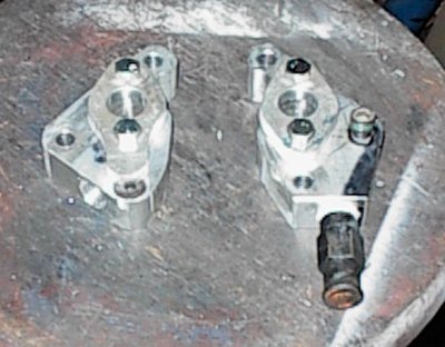 And here they are... the circle around the Allen bolt shows where it needs to
be counterbored. The passenger side adapter has a countersunk Allen to clear
the part of the spacer that covers the water pump bypass.
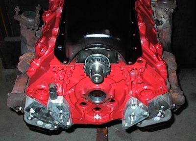 Skipping ahead a bit, here the adapters are, partway through final assembly.
The 1980 power steering pump brackets tuck the pump close in to the front of
the block; I rounded off the adapter to maximize clearance.
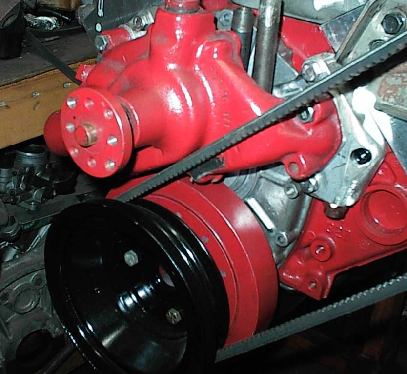 Here's the only real problem so far. The short pump is shaped differently
from the long pump, of course... the belt hits the body of the short pump. On
a long pump, the belt would be going under the snout with plenty of room.
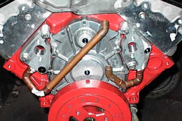 5/8" copper tubing for the water lines. These are the main lines coming out
of the block; each one handles the entire water flow for its side of the
engine. It doesn't look like enough, but it should be plenty. Most
thermostats have about the same area when open.
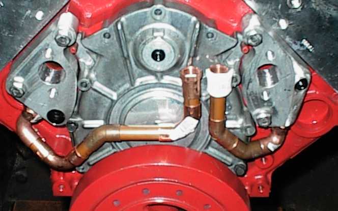 Turned up, with female NPT fittings for the hose barbs.
 The copper tubes need to be supported well or they might crack. First, we
start with a chunk of aluminum bar stock...
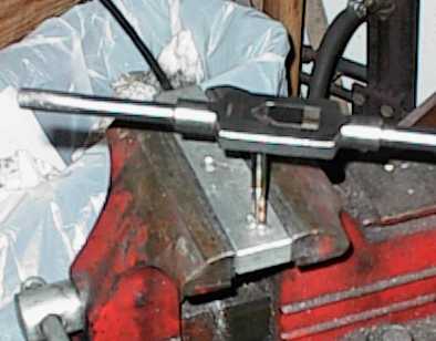 ...then we drill some holes, and tap some of them, so we can bolt two pieces
together...
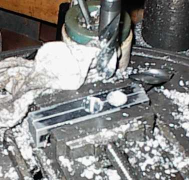 Then we drill some really big holes to run the copper fittings through.
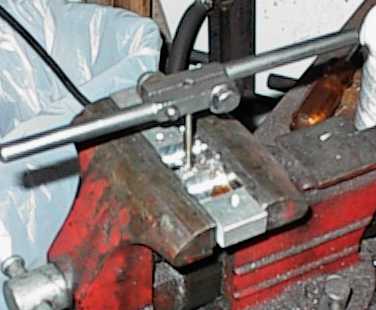 Tapping some different holes to hold the adapter to the mounting bracket.
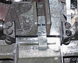 Sawing off some extra that we don't need...
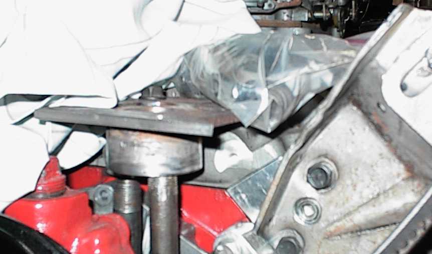 Pipes coming up to the bottom of the new thermostat housing, which is offset
off the intake manifold.
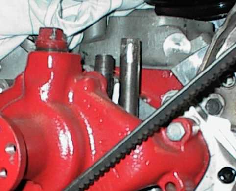
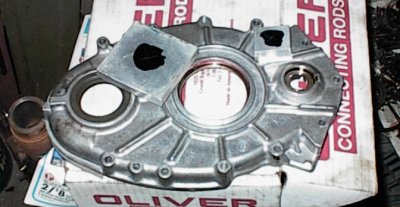 Since I wasn't planning to use either the distributor or water pump drives
from the LT1, the holes needed to be blocked off. You can't just change to a
different cover - nothing else fits an LT1. I started by cutting some chunks
of aluminum with the saw.
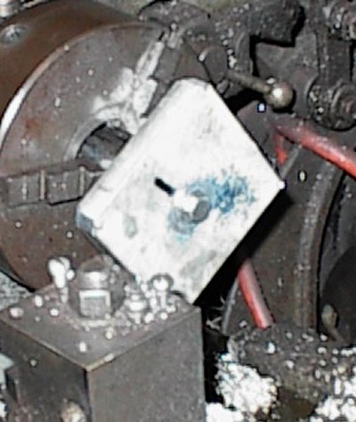 Turning square chunks to round chunks on the lathe. The holes in the cover
are stepped, with a rubber seal pressed in; I'm duplicating the step in the
plug.
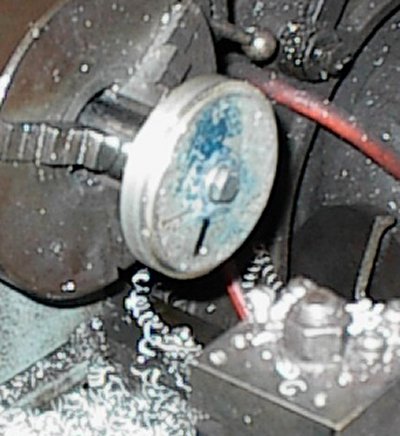 And here we are, finished...
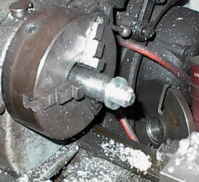 Upper plug in progress. It's a lot thicker than the large plug.
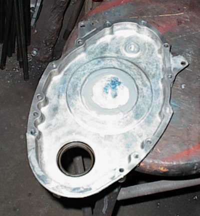 Here's the inside of the timing cover. The plugs are a snug fit, with epoxy
in the stepped area and epoxy on the back. A small button head screw will go
in each one to close off the threaded holes.
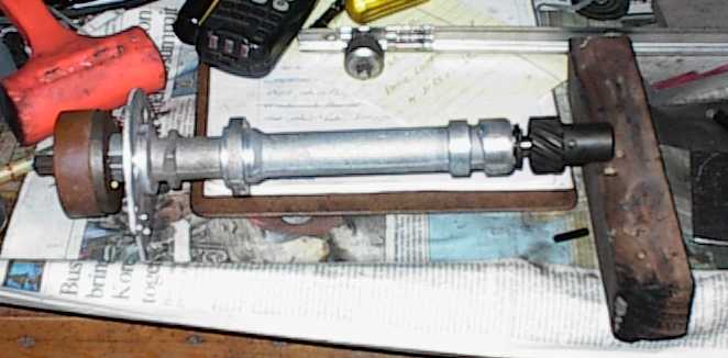 The LT1 has a little (plastic!) stub shaft that bolts down into the lifter
valley, with a gear to drive the oil pump. That gear is normally on the
distributor, but the LT1's distributor was up front.
Since we're going retro, I wanted to put an ordinary HEI in the back, which
would be easy since the Offy had a hole for it.
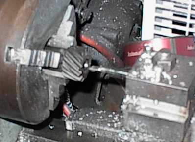 Having been burned on distributor gear mismatches before, at least on Fords,
where the incorrect gear will destroy both the gear and the camshaft, I pulled
the gear off the stub shaft to put on the HEI, so the cam would have the same
gear it left the factory with. No compatibility problems.
In their wisdom, Chevrolet made the inside diameter of the LT1's stub shaft
gear smaller than for a distributor! So I bored the thing out to fit.
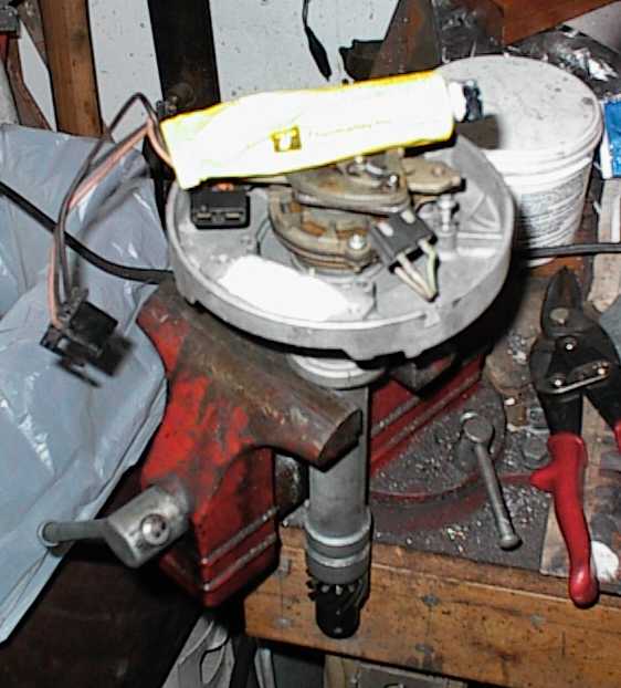 The HEI ignition module uses thermally-conductive grease to make a good
connection to the distributor housing, which it uses as a heat sink.
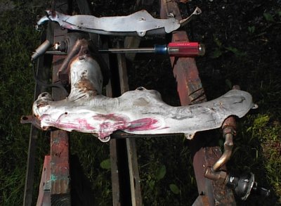 Corvette manifolds have siamesed center ports. Some were cast, some were
fabricated from tubing, and neither were much to brag about. The Camaro
manifolds are *much* better. Notice the dramatically upswept runners.
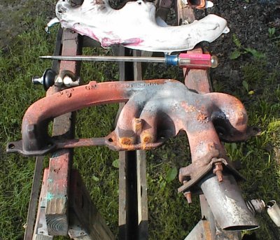 The heat shields were mangled in the crash, as was almost everything else. I
ground the rivet heads away to remove them.
The weird kink at the back is apparently to try to separate the last cylinder
from the first three. The first three do not overlap during the exhaust
event; the last one overlaps the next-to-last, so it comes in at a different
angle. Looks strange, but it's an attempt to reduce reversion into #5.
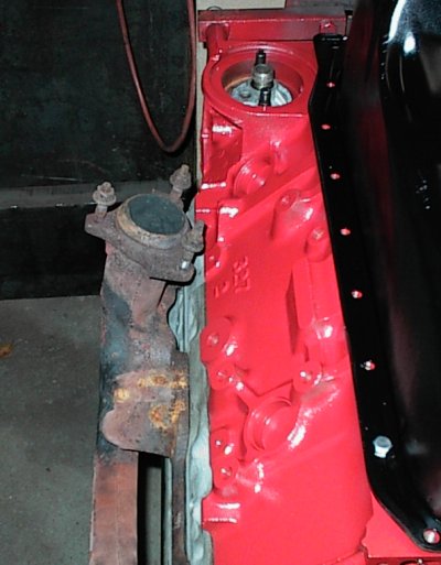 The Camaro manifolds tuck in close to the block. The Camaro's engine
compartment is fairly tight. The manifolds clear everything in the Malibu
just fine.
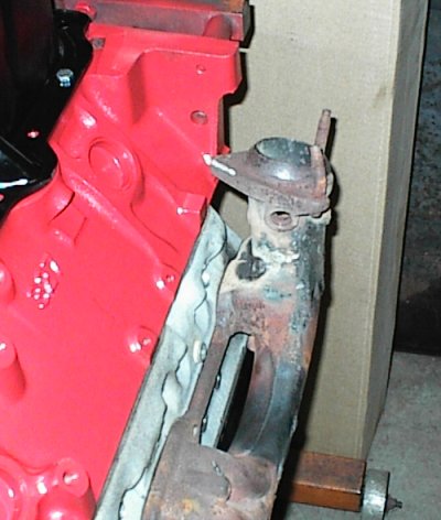 The passenger sides doesn't tuck in quite so tightly, but it's okay. The
bottom of the manifold was broken, along with so much else, in the crash. A
buddy used his stick welder and a nickel-iron rod to stick it back together.
Both manifolds will get new brass studs before the engine goes in.
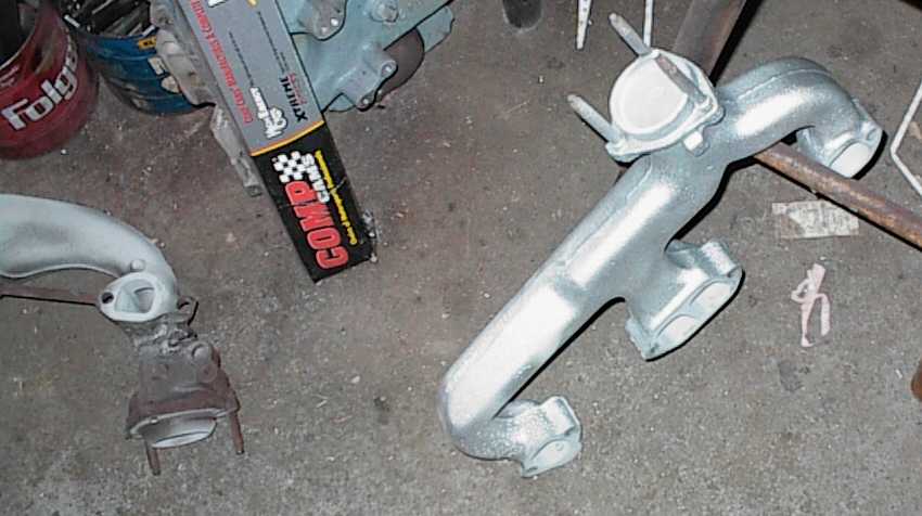 I couldn't use the driver's side manifold because the V6 air conditioning
compressor already occupied that space. So I found a '94 Vortec pickup truck
exhaust manifold. It has a 2-1/4" outlet,
same as the LT1 manifold. There was a rusty heat shield that I discarded.
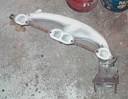 LT1 manifold, sandblasted and ceramic coated. No paint yet. Of course, the
manifold I had to replace was the one that wasn't broken...
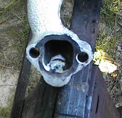 There was a big A.I.R. boss in the truck manifold. I welded a plug in, then
ground the boss out.
Ink and scribe lines are for porting the manifold to match the LT1 exhaust
ports. In their ultimate wisdom, GM raised the exhaust ports a bit on the LT1
to improve exhaust flow. But they didn't bother to raise the bolt pattern, so
there's a nasty step at the top if you bolt an early manifold or header to an
LT1 head.
 The A.I.R. boss referred to previously.
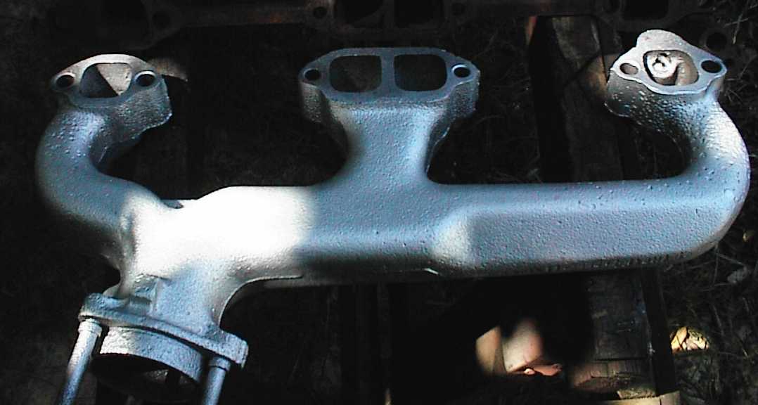
 The truck manifold is "Chevelle style" as I think of it, sweeping underneath
the spark plugs. All factory applications of this type of manifold have heat
shields to keep from cooking the plug wires.
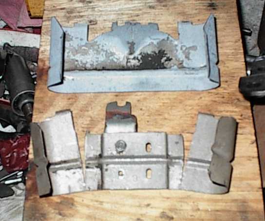
The LT1 heads have angled spark plugs, which are also relocated to the exhaust
side of the combustion chamber. Standard heat shields hit the plugs. So I
cut and spliced them to get clearance.
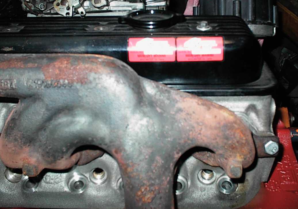 Mercury Marine valve covers say "250HP." Hey, close enough...
 The stock LT1 exhaust heat shields were torn up in the crash, so I made some
cardboard templates to make some new ones. Some GM applications don't use
shields, but those are prone to burn up valve cover gaskets. Yes, even the
fancy silicone rubber gaskets can char and break up!
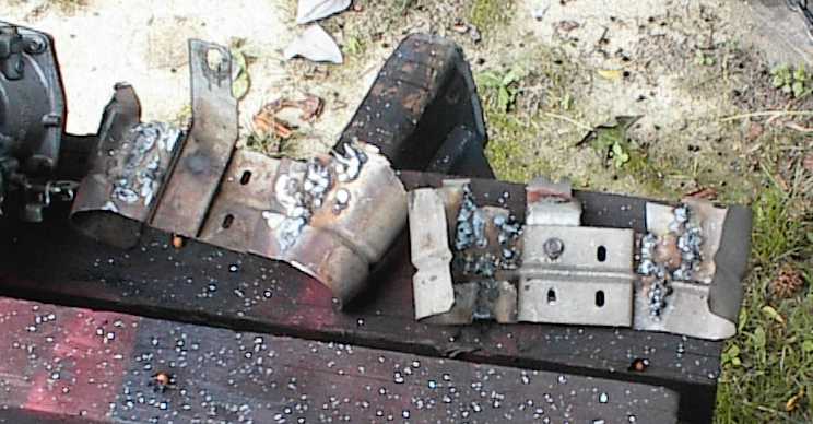 Whatever alloy Chevy used didn't want to weld worth flip. It took a lot of
grinding to smooth them out.
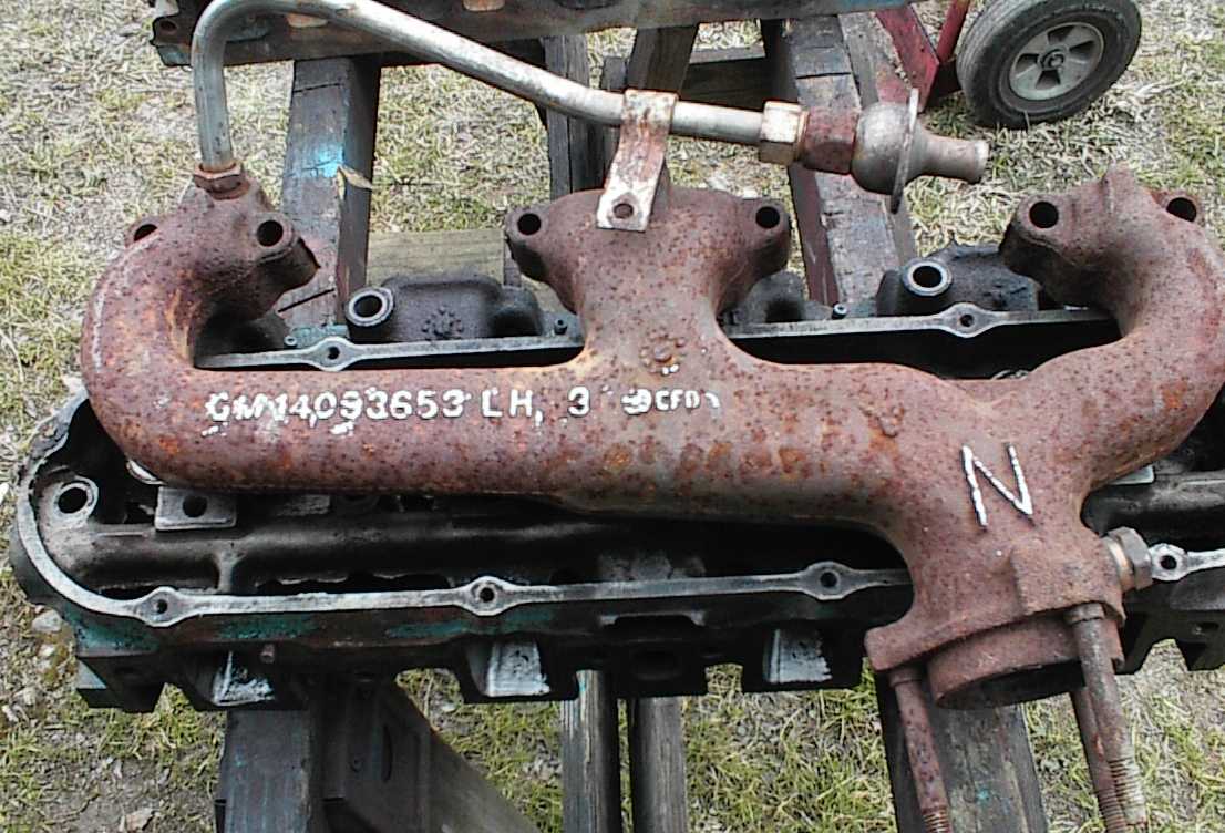 I dug through the manifold pile at the local yard and found his - a 1992
Chevrolet 3/4 ton pickup truck manifold. It's virtually identical to any
early truck manifold, except it has a 2-1/4" outlet. Early ones were 1-3/4 or
2"
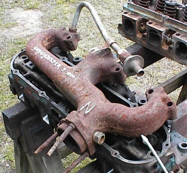 O2 sensor bung in the back, should clear the Malibu firewall okay.
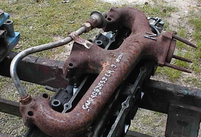 There had been a heat shield wrapped around the front part. It had mostly
rotted away. There were some deep pits where the shield had been, but they
weren't bad enough to discard the manifold.
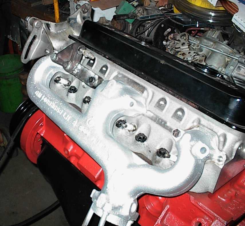 Here's the truck manifold with the AC bracketry in place.
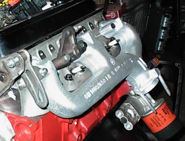 ...and a view from the other end.
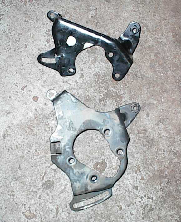 The top bracket is an '80 Malibu power steering pump bracket. Brand new, too.
The bottom bracket is off an '89 Suburban with a 350. It bolts up perfectly
to the air conditioner part of the bracket, and has the same water pump part
as the V6 bracket. However, it has an extension below for an extra bracket,
that bolts to the block. The Malibu brackets are known for cracking; the
truck bracket appears to be an update. So I'll be using the truck bracket.
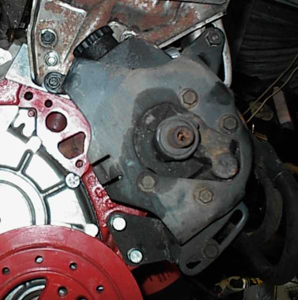 Here is is, installed. You can see the extra brace bolted to the block.
Unfortunately, the pump's tank hits the water pump adapter.
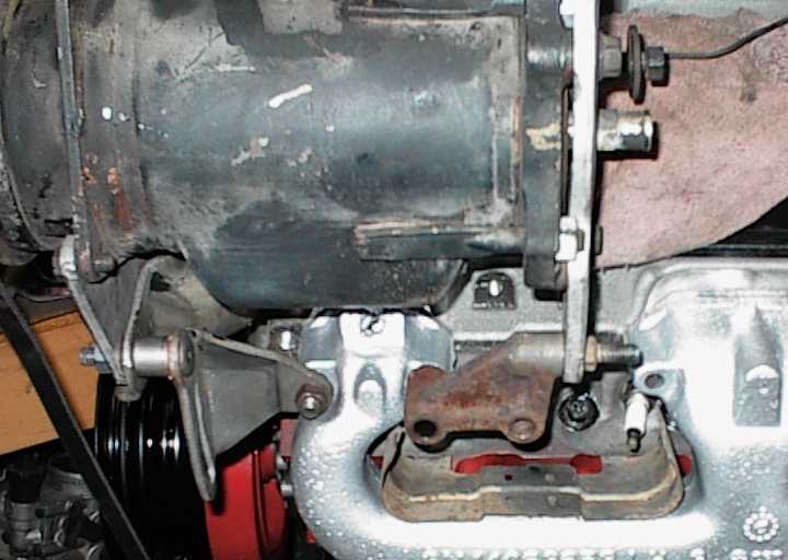 Here's the V6 compressor bracket. On the V6, it spans two exhaust manifold
bolts, which are spaced closer than the V8 bolts. The front bolt hole is
okay, but the rear hangs off into empty space.
I scrounged several V8 brackets, but the compressor pivot was in the wrong
place. So, off to modify the V6 bracket...
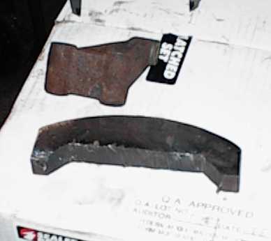 A chunk of 3/4 inch steel was available. Sharp viewers will notice that it's
one of the counterweights from my 2.5 four cylinder balance experiment.
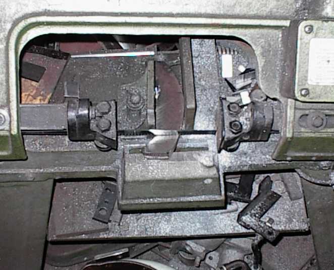 We saw the chunk into the approximate shape before moving to the milling
machine.
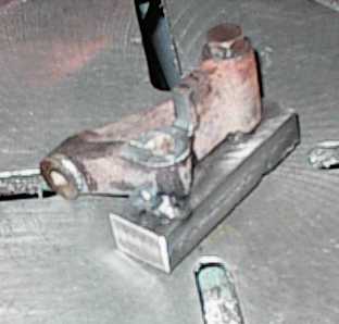 I needed a big notch milled in the casting, but there was no way to hold it in
the vise in the right orientation. So I bolted and tack welded it to a chunk
of steel and held on to that instead.
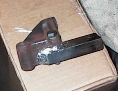 Here's the V6 casting welded to our chunk of machined steel. The bolt kept
them together and in alignment for welding.
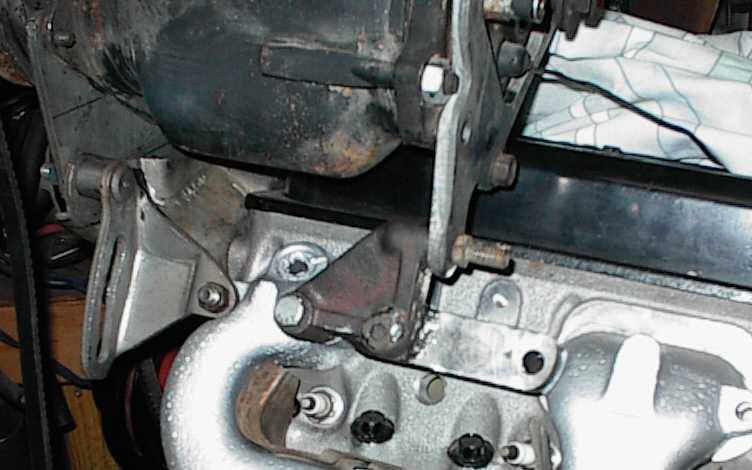 Finished lower bracket, with socket head cap screw torqued to 45 ft-lb and
welded in place, and the end ground to clear the pocket in the exhaust
manifold.
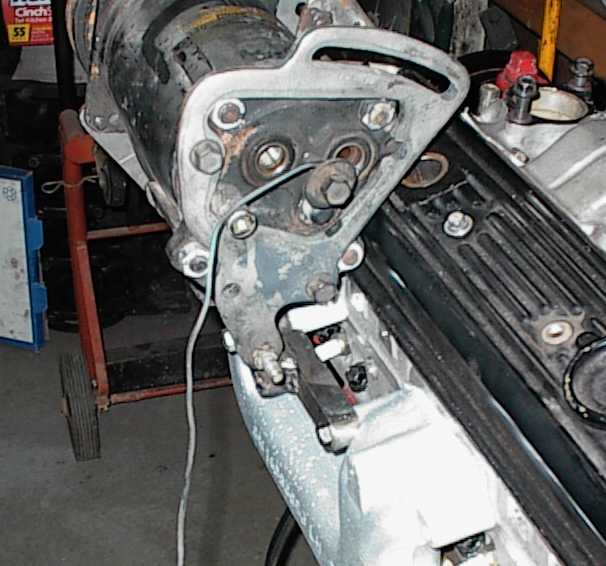 Another view of the bracket. It ought to be plenty strong. It has to be; the
old A6 compressor is pretty heavy!
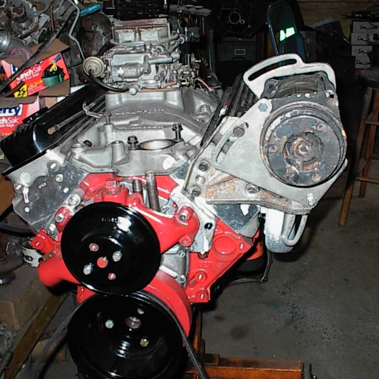 Front view of AC bracketry. This is all V6 Malibu stuff. I haven't done the
rear-upper bracket yet. Nothing is even close to matching the Offy intake to
the V6 AC compressor location, so that'll be a scratchbuilt part.
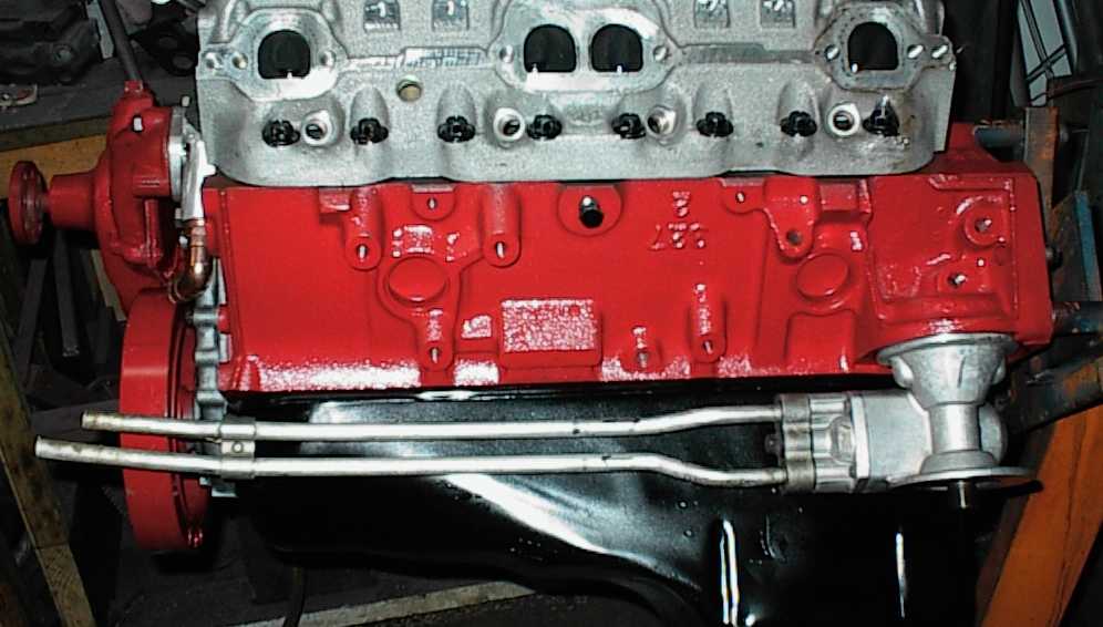 This is the LT1's oil cooler. The aluminum lines are brazed to the adapter,
and had rubber lines swaged to the ends, one going to the Camaro radiator, one
going to the LT1 water pump.
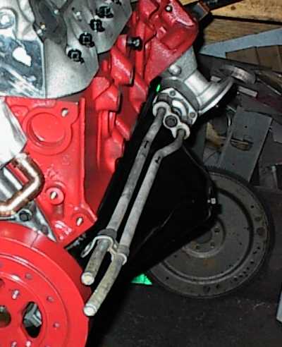 A short oil filter has to be used with the oil cooler.
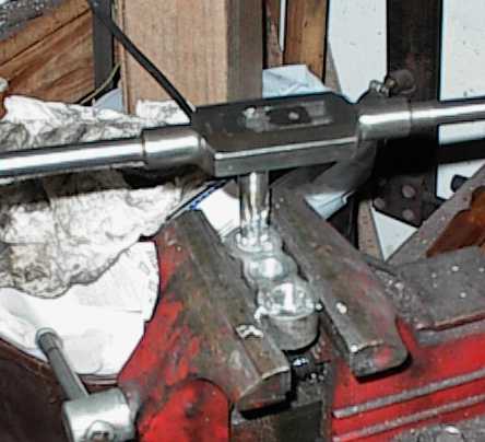 I cut the aluminum tubes off, then tapped the adapter block for 3/8 NPT
fittings.
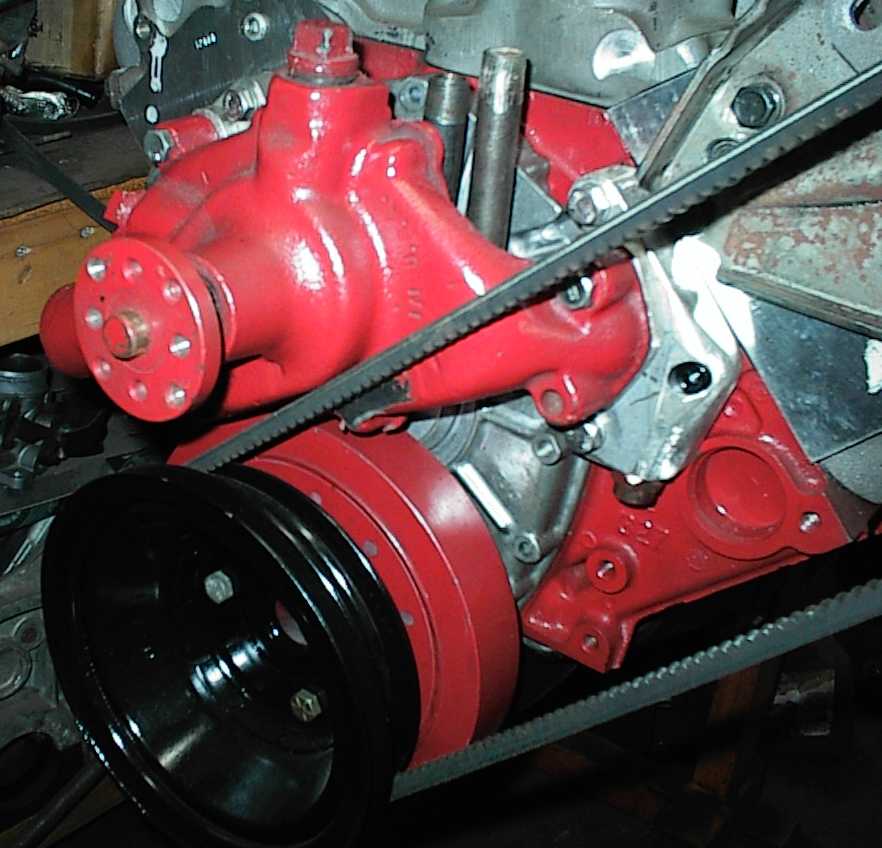 Problem with the AC belt - it rubbed the water pump. There wasn't enough
metal in the casting to grind adequate clearance. Drat!
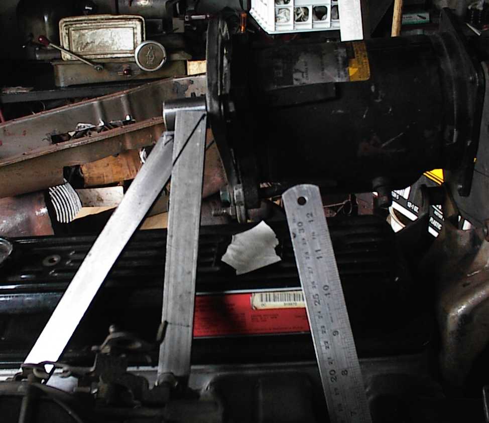 Upper AC compressor bracket. I made 1" standoffs to raise the flat parts over
the valve cover, then bolted them to the bosses on the Offenhauser manifold.
A piece of 1" bar stock was tapped for a 3/8" bolt. The braces themselves are
1/4" x 1" cold rolled steel. I had to bend a twist them slightly to align
things, so they look a little odd compared to the usual stamped steel brace.
However, it should be plenty strong, which is good enough.
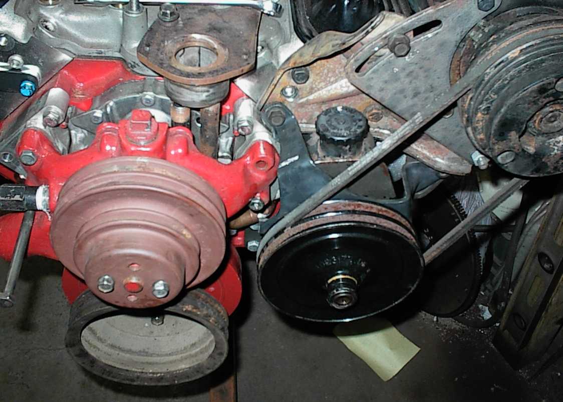 New plan for the AC belt. A 403 Olds yielded a double-groove power steering
pulley. I can drive the power steering pump from the crank, and then the
compressor from the pump. With 180 degrees of wrap for each belt, it should
work okay.
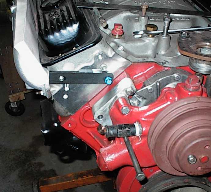 Getting started on the alternator bracket. 5/16" x 1" flat is bolted to the
head. It took a header bolt to clear the block on the inboard side.
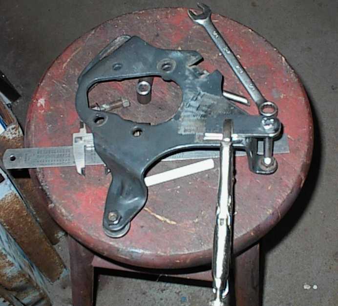 The power steering pump bracket got a tab welded on for the slotted alternator
bracket. I welded a tube in after welding the tab. One bolt goes through the
whole thing, including the alternator bracket.
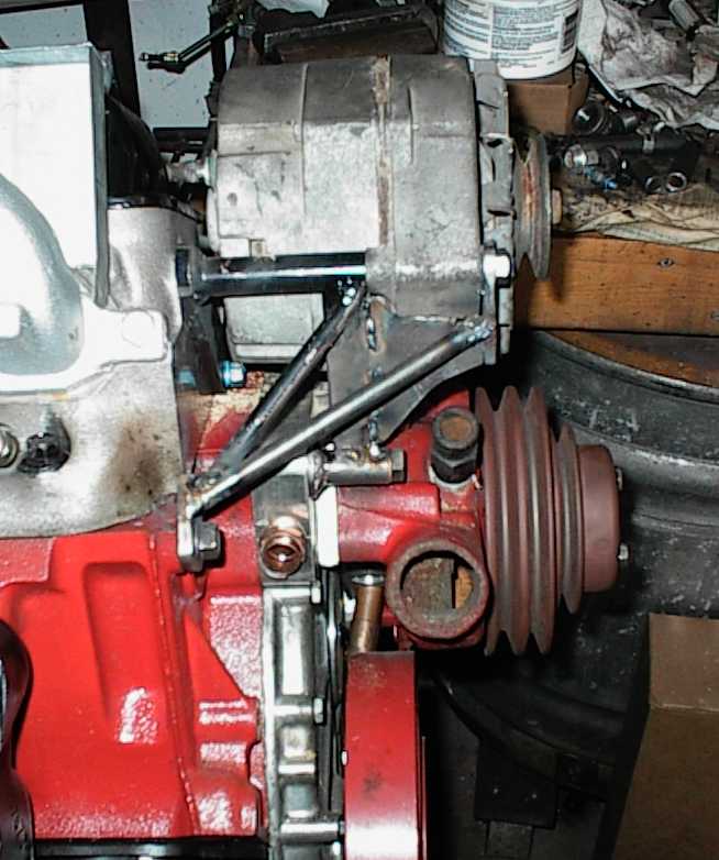 This is the finished bracket. It's as fully triangulated as I could come up
with. As you may have noticed from this page, I have a fetish about not
having important engine accessories fall off.
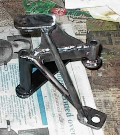 Bizarre-looking bracket prior to finish grinding and painting.
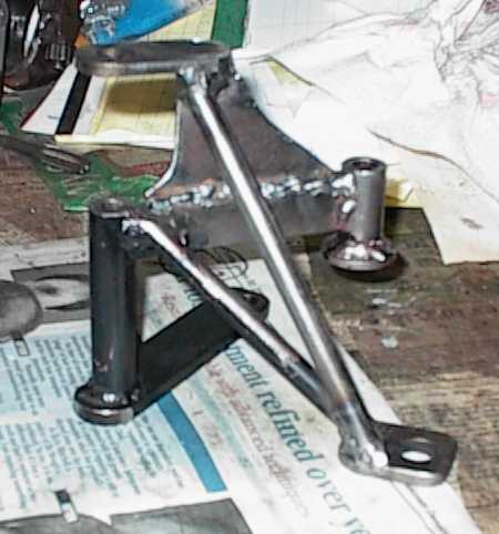 Another angle. Ugly, isn't it?
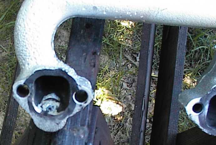 You can see how I've started porting the exhaust manifold to match the LT1
heads. It's upside down, of course, but you can see the raised and rounded
port roof coming in. I ground all the big knob for the air bung out after
welding up the hole.
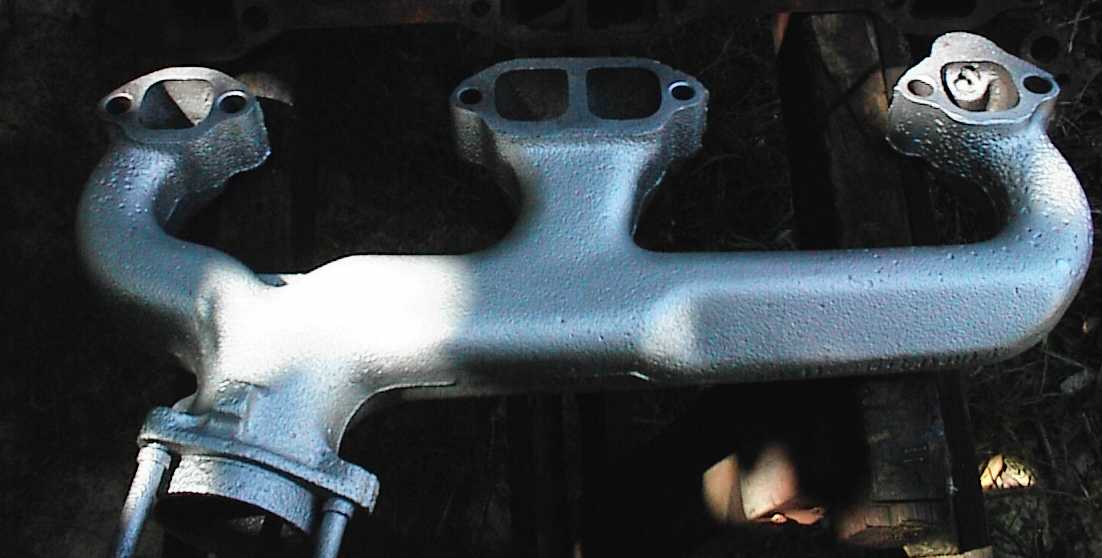 Backside of LH manifold. The two center ports are siamesed. As far as I can
tell, all of the manifolds of this type were made that way. I'd never paid
attention before. The proximity of the spark plugs cramps space for the
center runners, and the cylinders fire 360 degrees apart anyway, so it makes
little difference to power, though it causes the center two valves to run a
bit hotter.
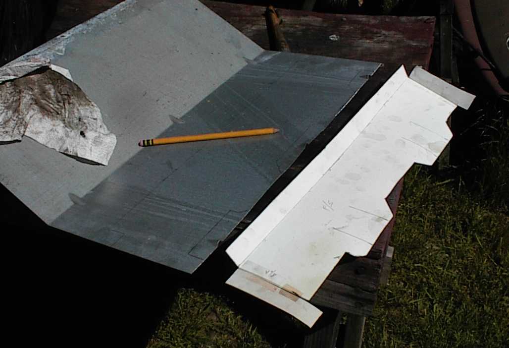 The upswept LT1 right hand exhaust nearly touches the valve cover. The
stainless steel OEM heat shield was enough to keep from cooking the gasket,
but since the ruined shield had to be removed, I made a simple box shaped heat
shield. This is the cardboard pattern and the piece of scrap steel sheet I
used.
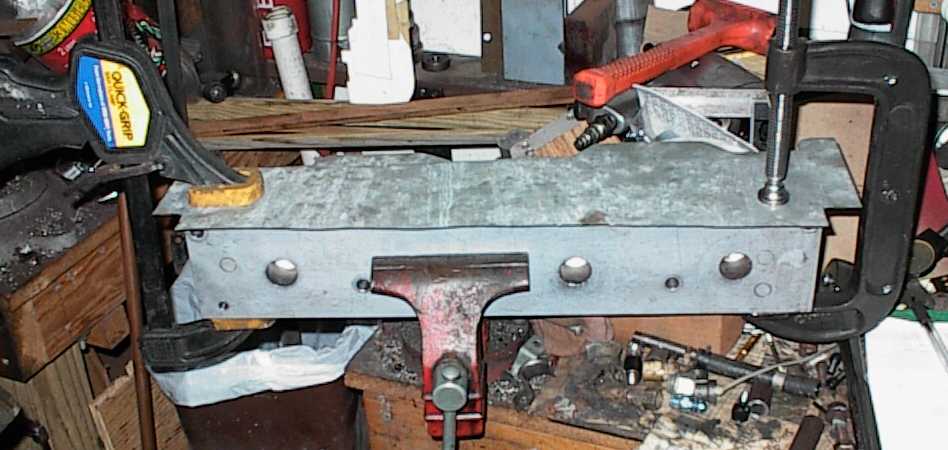 I traced the pattern onto the steel, cut it out with tin snips, and here I
have it clamped to a rectangular steel bar. I folded the corners with a
rubber mallet.
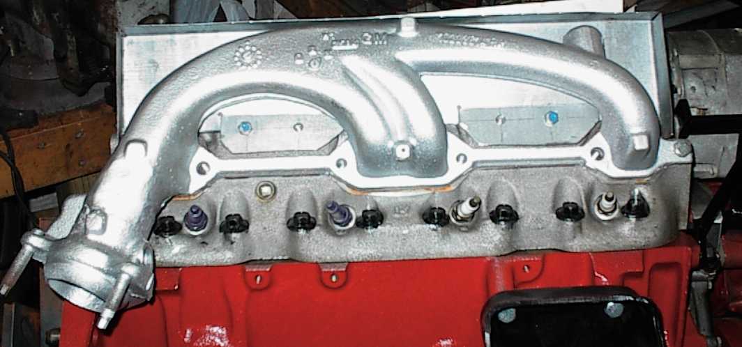
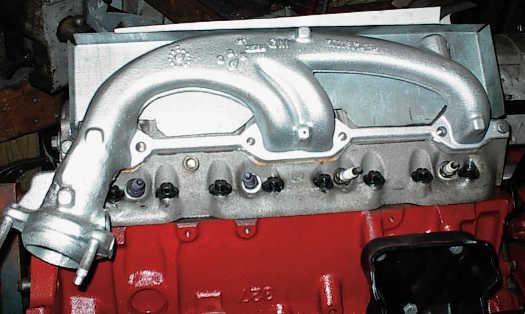 Here's the back panel. The tabs hanging down will get drilled for mounting
bolts.
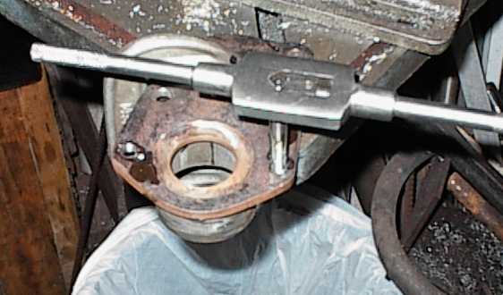 Tapping the thermostat adapter for the thermostat housing.