As circumstances worked out, he wound up not being able to attend the event, but at least now he has a spare engine...
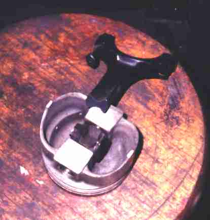 The engine had two badly munged rods. We wanted to save the pistons, which
were original 29-year-old BOSS 351 forgings. Ford used a *lot* of
interference fit on 351 Cleveland wristpins - .002 to .0025" instead of the
usual .001-.0015". I sawed the shank of the rod off to make the piston easier
to fixture in the press and machined a button to go into the end of the fancy
taper-wall wristpin to keep from munging it. The bandsaw blade practically
fell through the rod; it's a 1041-H steel forging, but very soft.
The engine had two badly munged rods. We wanted to save the pistons, which
were original 29-year-old BOSS 351 forgings. Ford used a *lot* of
interference fit on 351 Cleveland wristpins - .002 to .0025" instead of the
usual .001-.0015". I sawed the shank of the rod off to make the piston easier
to fixture in the press and machined a button to go into the end of the fancy
taper-wall wristpin to keep from munging it. The bandsaw blade practically
fell through the rod; it's a 1041-H steel forging, but very soft.
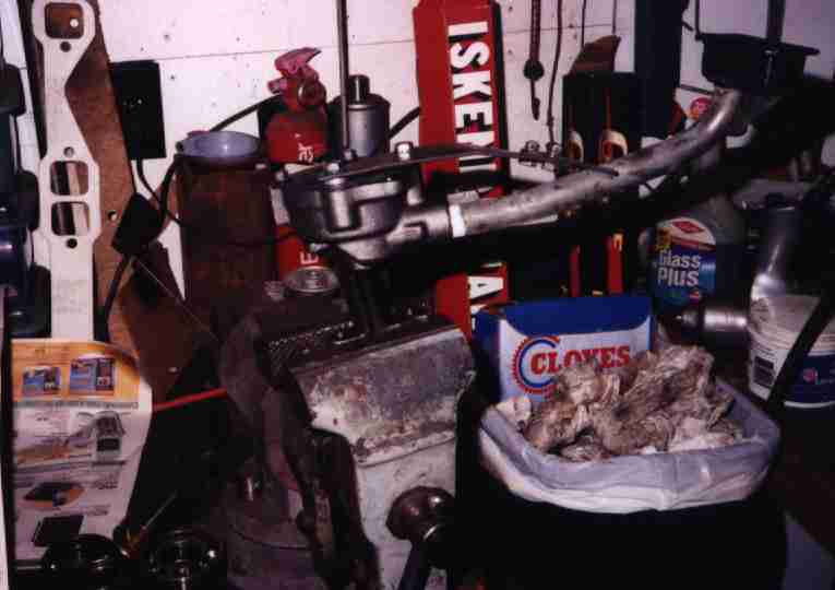
My wooden stool provides a convenient workspace as well as a place to take
pictures. Using the torch to burn some broken bolts out of some turbocharger
housings hasn't helped its looks any. But hey, it works, and I even sit on it
sometimes.
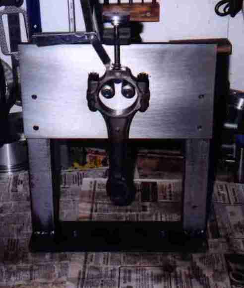 Checking the rods for squareness. This fixture locates on the big end bore;
the feeler gauge tells if the bore is square to the sides. Another fixture
checks the alignment of the big and small ends. All the rods were fine.
Checking the rods for squareness. This fixture locates on the big end bore;
the feeler gauge tells if the bore is square to the sides. Another fixture
checks the alignment of the big and small ends. All the rods were fine.
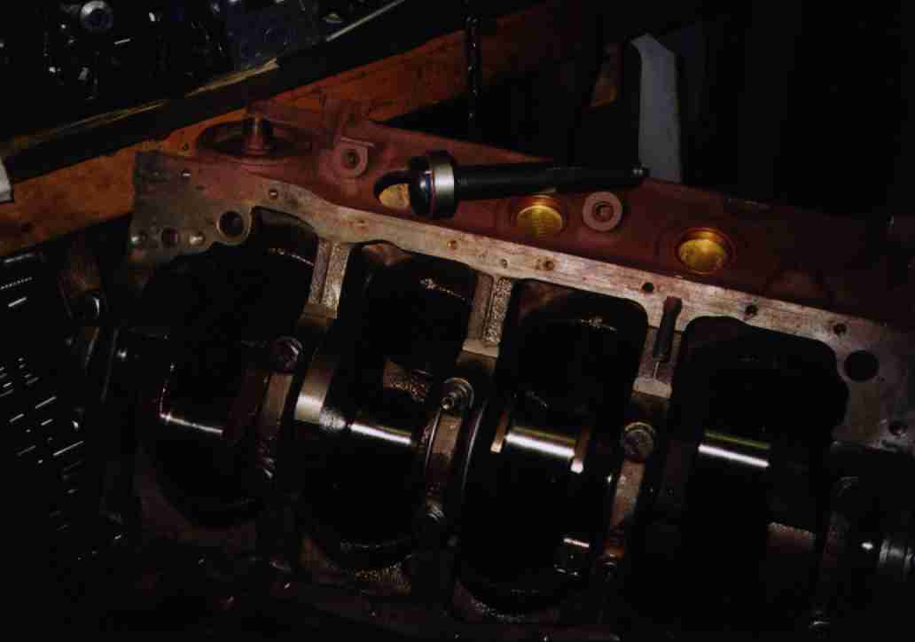
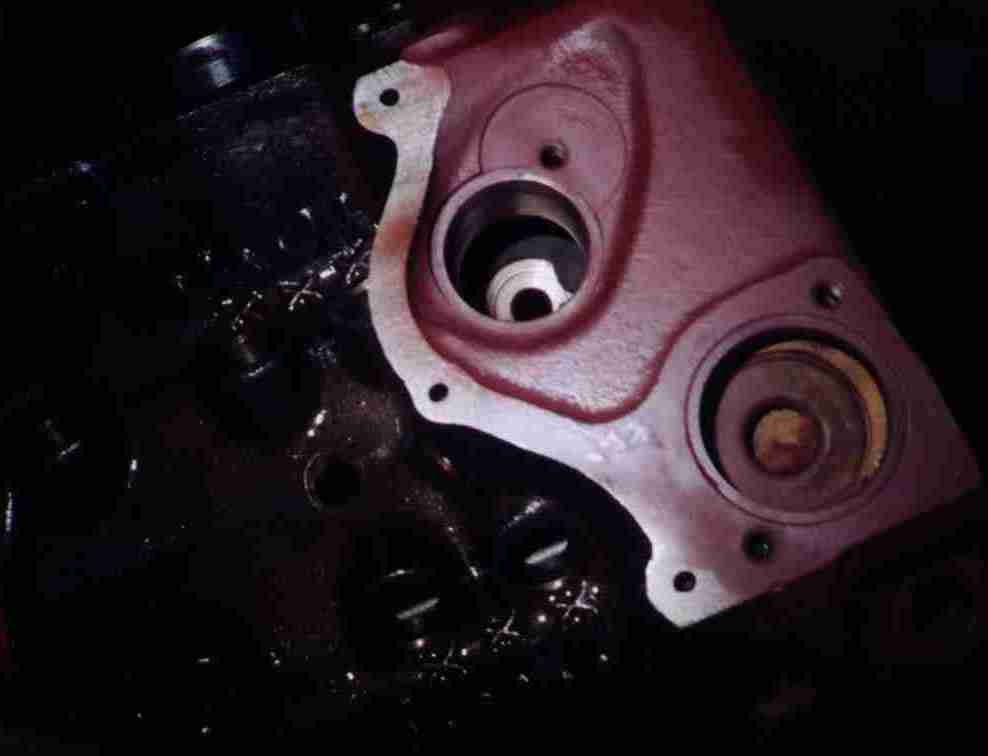 I drilled a small oil hole from the distributor shaft oil gallery to
underneath the distributor gear, for positive lubrication of the gear. This
excellent shot just barely shows the edge of the hole. Well, it looked fine
through the viewfinder...
I drilled a small oil hole from the distributor shaft oil gallery to
underneath the distributor gear, for positive lubrication of the gear. This
excellent shot just barely shows the edge of the hole. Well, it looked fine
through the viewfinder...
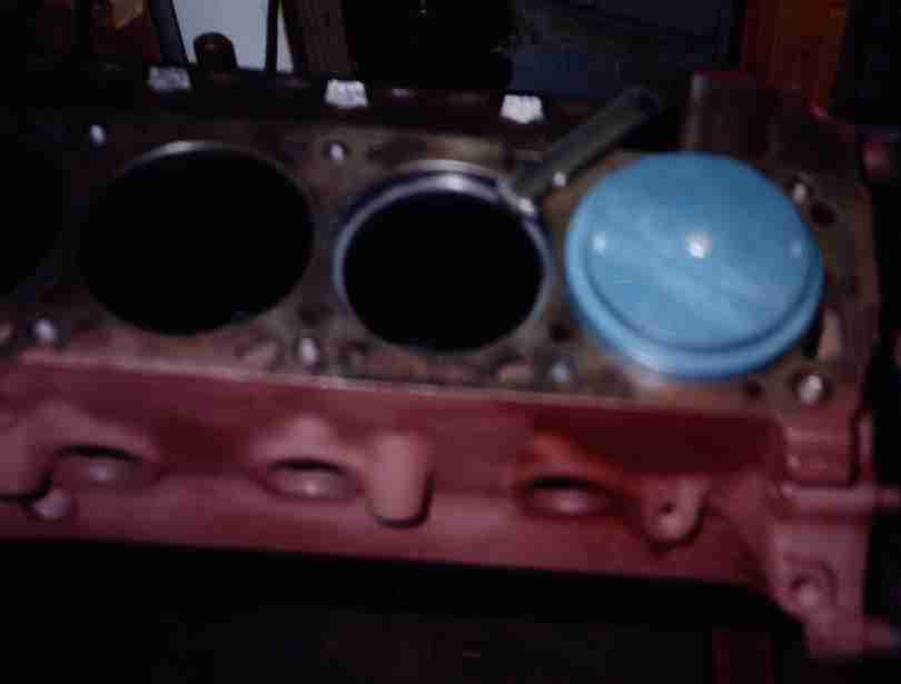
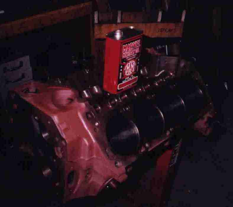 The block was a standard bore Cleveland with little wear. There were some
scratches on the cylinder walls where some flak from the disintegrated
distributor gear had got wedged in between the pistons and bores. Lots can
happen at 6500 RPM before you can shut an engine down. I did a light touch-up
hone, then the tedious procedure of mopping out the bores with light oil
(Marvel Mystery Oil in this instance, though automatic transmission fluid
works fine) and paper towels. You'd be surprised at the silvery stuff that
hides in the imperceptible roughness of an apparently-smooth cylinder.
The block was a standard bore Cleveland with little wear. There were some
scratches on the cylinder walls where some flak from the disintegrated
distributor gear had got wedged in between the pistons and bores. Lots can
happen at 6500 RPM before you can shut an engine down. I did a light touch-up
hone, then the tedious procedure of mopping out the bores with light oil
(Marvel Mystery Oil in this instance, though automatic transmission fluid
works fine) and paper towels. You'd be surprised at the silvery stuff that
hides in the imperceptible roughness of an apparently-smooth cylinder.
 Gapping the rings. The plastic tool pushes the rings down square with the
bore, and you use a feeler gauge to measure the gap. File-them-yourself rings
cost two to three times what "ready to run" rings do. Go figure...
Gapping the rings. The plastic tool pushes the rings down square with the
bore, and you use a feeler gauge to measure the gap. File-them-yourself rings
cost two to three times what "ready to run" rings do. Go figure...
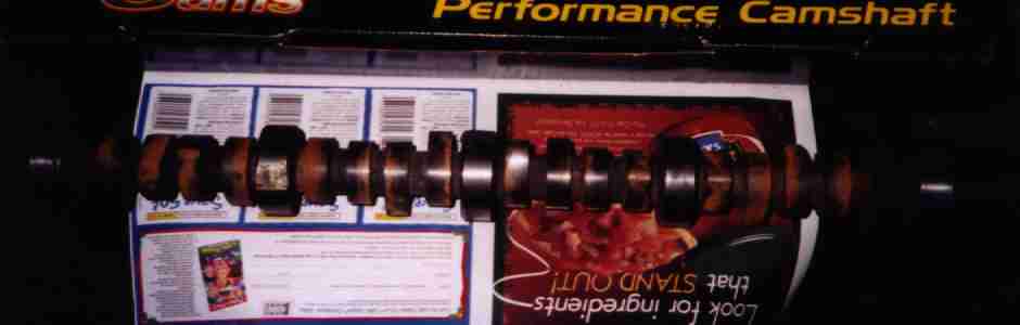
 Checking the pushrod length. We replaced the troublesome roller cam with a
somewhat milder solid flat tappet cam. The base circle and lifter heights
were different than the rollers, requiring new pushrods.
Checking the pushrod length. We replaced the troublesome roller cam with a
somewhat milder solid flat tappet cam. The base circle and lifter heights
were different than the rollers, requiring new pushrods.
This is all done during one of the trial assemblies. You usually wind up with
two or three trial fits before you clean everything up for the final assembly.
 We didn't need the gigondomundo valve springs the roller cam required, so we
got springs more suitable for the new cam.
We didn't need the gigondomundo valve springs the roller cam required, so we
got springs more suitable for the new cam.
 The new valve springs didn't fit the retainers, so we Mike ordered a fresh set
of titanium retainers to fit the springs. And the shin bone is connected to
the ankle bone...
The new valve springs didn't fit the retainers, so we Mike ordered a fresh set
of titanium retainers to fit the springs. And the shin bone is connected to
the ankle bone...
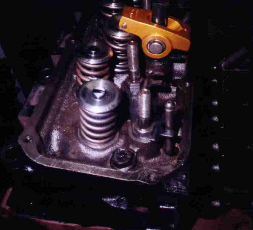
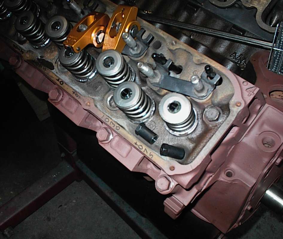 This picture is supposed to show you how the rocker wipe patterns are
nicely centered on the valve stems. The secret engine builder dye is ordinary
black Magic Marker. The guide plates also get tapped left and right to center
the rockers up on the stems.
This picture is supposed to show you how the rocker wipe patterns are
nicely centered on the valve stems. The secret engine builder dye is ordinary
black Magic Marker. The guide plates also get tapped left and right to center
the rockers up on the stems.
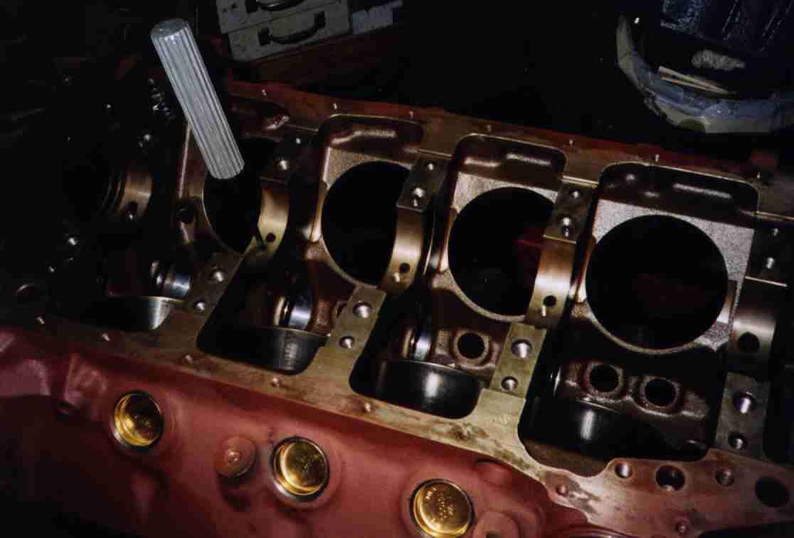
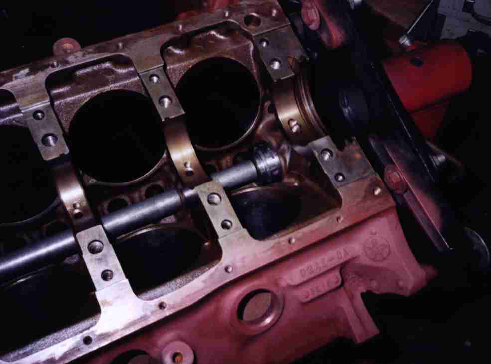 Installing the cam bearings with an expandable mandrel. You can see the
tapped holes for the oil restrictor plugs too. The BOSS 351's four bolt block
is no different than any other four bolt Cleveland block.
Installing the cam bearings with an expandable mandrel. You can see the
tapped holes for the oil restrictor plugs too. The BOSS 351's four bolt block
is no different than any other four bolt Cleveland block.
The cam bearings had been removed when Mike had the block cleaned. Ford is
notorious for having cam bearing bore alignment problems - the factory bores
the block from both ends, installs undersize bearings, and align-bores the
bearings. I guess it makes sense to some bean-counter at Ford. Anyway, the
new camshaft wouldn't go in, so I had to align-ream the bearings. The tool
shaved just a little bit off the #1 bearing. Journal to bearing clearance was
still on the tight side, so there won't be any trouble. I'd heard about the
Cleveland alignment problems from several places, but this was the first time
I actually encountered it.
 This is the special camshaft reaming tool. Most shops windup with a
collection of these things, for different engines. You take an old cam and
notch the bearing journals with the angle grinder to make a single tooth
reamer. Just wipe some grease into the tooth to hold the chips, insert,
rotate a couple of times, and you're done.
This is the special camshaft reaming tool. Most shops windup with a
collection of these things, for different engines. You take an old cam and
notch the bearing journals with the angle grinder to make a single tooth
reamer. Just wipe some grease into the tooth to hold the chips, insert,
rotate a couple of times, and you're done.
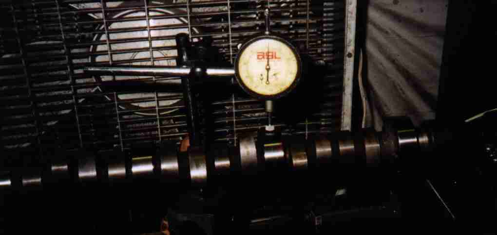 Checking the cam for warpage. .0015" Total Indicated Runout; that's actually
pretty good. All cams warp some when they're heat treated.
Checking the cam for warpage. .0015" Total Indicated Runout; that's actually
pretty good. All cams warp some when they're heat treated.
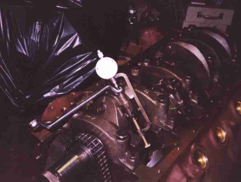
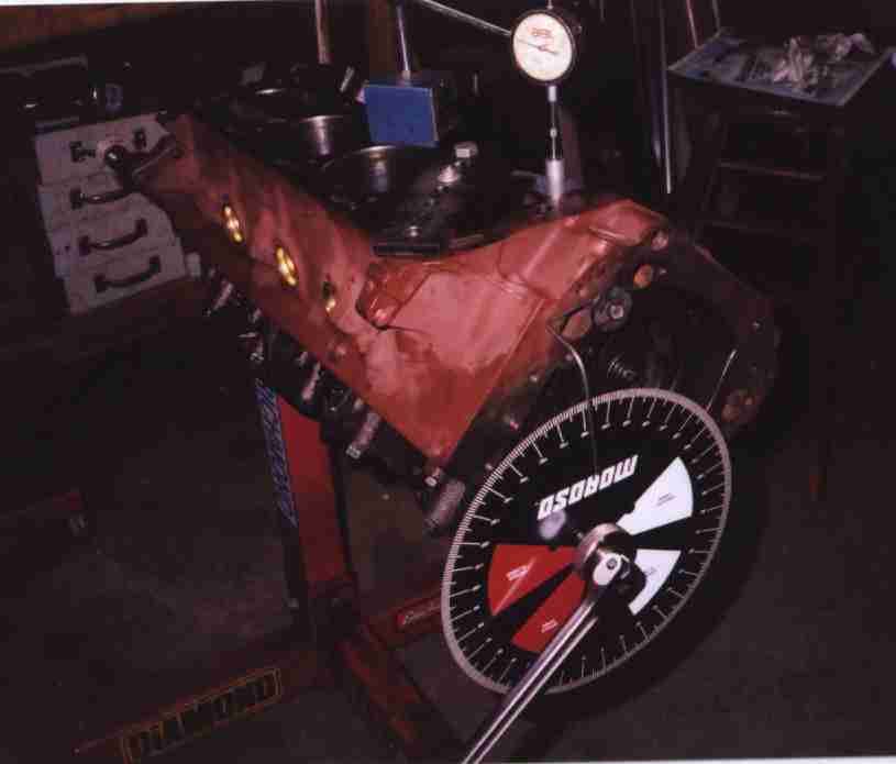 Degreeing the cam. Use the piston stop to find TDC, set up the indicator,
cha-cha this way, cha-cha that way, addition and division, yee hah. The cam
was off about a degree and a half. Most cams come in zero, or close to it,
but I've seen lots worse. A degree and a half is nothing to worry about, so I
didn't check further (to find out if the error was in the cam or timing set),
or use indexing bushings.
Degreeing the cam. Use the piston stop to find TDC, set up the indicator,
cha-cha this way, cha-cha that way, addition and division, yee hah. The cam
was off about a degree and a half. Most cams come in zero, or close to it,
but I've seen lots worse. A degree and a half is nothing to worry about, so I
didn't check further (to find out if the error was in the cam or timing set),
or use indexing bushings.
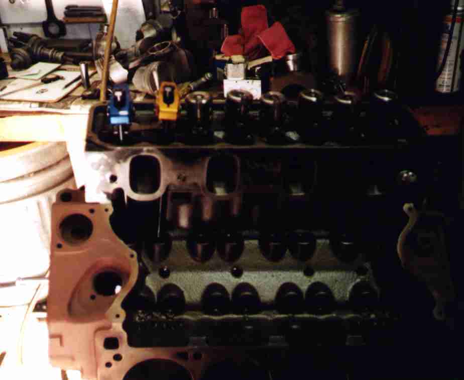
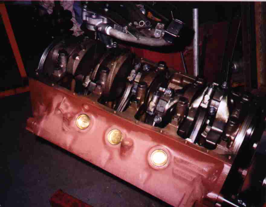
 All the trial fitting is done. Now we're ready to begin assembly for real..
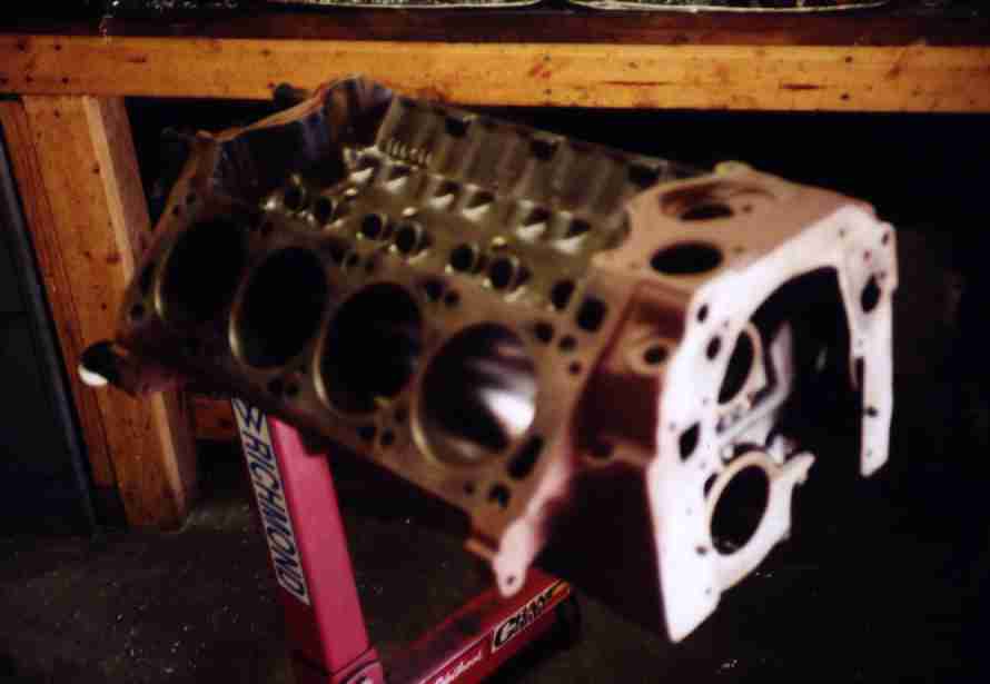
Block all cleaned and ready for assembly. The ugly red paint is Rust-Oleum
Rusty Metal Primer. I use that for engines that the owner will paint later.
You can't leave anything unoiled or unpainted here in the swamplands or it'll
turn into a mass of rust within days.
All the trial fitting is done. Now we're ready to begin assembly for real..
Block all cleaned and ready for assembly. The ugly red paint is Rust-Oleum
Rusty Metal Primer. I use that for engines that the owner will paint later.
You can't leave anything unoiled or unpainted here in the swamplands or it'll
turn into a mass of rust within days.
 Freeze plug installation. I made up a whole bunch of drivers in various sizes
for this sort of thing. Brass freeze plugs are only a few bucks more than
steel and won't rust through like the steel plugs tend to do.
Freeze plug installation. I made up a whole bunch of drivers in various sizes
for this sort of thing. Brass freeze plugs are only a few bucks more than
steel and won't rust through like the steel plugs tend to do.
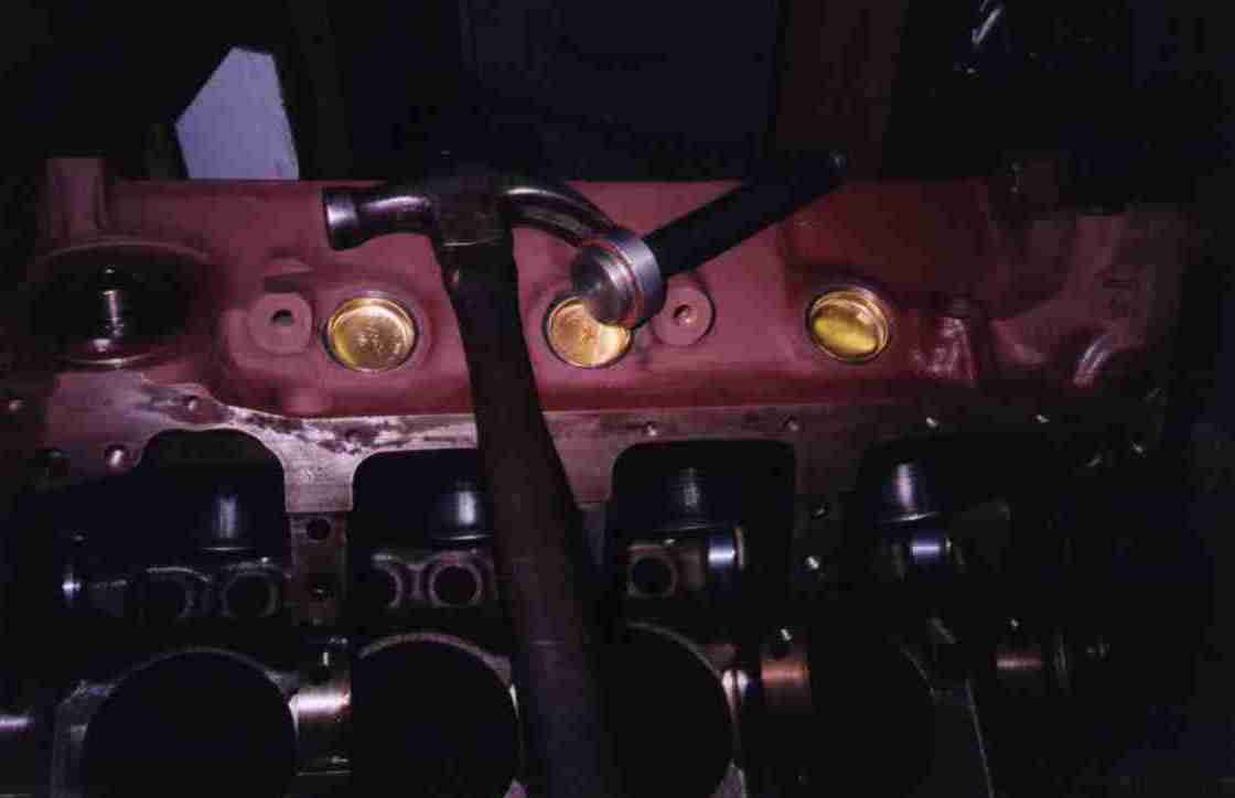
 I'm installing the oil restrictors here. They reduce the oil flow to the cam
bearings and the driver's side lifter gallery. This diverts some oil from
upstairs to the rod and main bearings.
I'm installing the oil restrictors here. They reduce the oil flow to the cam
bearings and the driver's side lifter gallery. This diverts some oil from
upstairs to the rod and main bearings.
 Crank is installed next...
 Tightening the rod bolts. ARP provides a special moly lube, and you stretch
the bolts to .0065". It's more consistent than using a torque wrench, but
it's a pain in the ass juggling the dial indicator, a box end wrench, and a
piece of pipe over the end of the wrench.
Tightening the rod bolts. ARP provides a special moly lube, and you stretch
the bolts to .0065". It's more consistent than using a torque wrench, but
it's a pain in the ass juggling the dial indicator, a box end wrench, and a
piece of pipe over the end of the wrench.
 Just a generic assembly shot. Rings are gapped, clearances checked, all that
stuff.
Just a generic assembly shot. Rings are gapped, clearances checked, all that
stuff.
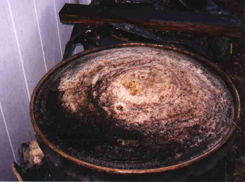 I left the heads in the caustic tank and sort of forgot about them. In an
Arkansas winter, that can cause problems. Like when 300 pounds of caustic
freezes the heads into a giant ice cube. Fortunately the ice was porous and
soft, so I just waited until it thawed instead of switching on the heater to
suck up a bunch of that Entergy 18.4c/kWh electricity. I'd love to get some of
that 4c/kWh electricity the electric car guys keep yapping about...
I left the heads in the caustic tank and sort of forgot about them. In an
Arkansas winter, that can cause problems. Like when 300 pounds of caustic
freezes the heads into a giant ice cube. Fortunately the ice was porous and
soft, so I just waited until it thawed instead of switching on the heater to
suck up a bunch of that Entergy 18.4c/kWh electricity. I'd love to get some of
that 4c/kWh electricity the electric car guys keep yapping about...
 Mike had sent the heads out for work some years before. The shop installed
Winona wire guide inserts to bush the guides down from 11/32 to 5/16 and
installed 5/16" stem stainless valves. Unfortunately, the fit was loosey-
goosey at .005" or so, and there were oil crusts on the valve stems and in the
ports where oil had blithered down there. You pull the Winona guides out just
like big Heli-Coils. Note: they're sharp as hell. After applying several
Band-Aids, I realized I had a problem. I didn't have the tooling to install
Winona liners, but it never occurred to me nobody else in the area would
either. And you can't just drive in new K-Line type thinwall sleeves, because
the Winona threading operation opens the guide up too big for it to stay in.
I eventually found some .060" thick sleeves instead of the normal .030".
Whew!
Mike had sent the heads out for work some years before. The shop installed
Winona wire guide inserts to bush the guides down from 11/32 to 5/16 and
installed 5/16" stem stainless valves. Unfortunately, the fit was loosey-
goosey at .005" or so, and there were oil crusts on the valve stems and in the
ports where oil had blithered down there. You pull the Winona guides out just
like big Heli-Coils. Note: they're sharp as hell. After applying several
Band-Aids, I realized I had a problem. I didn't have the tooling to install
Winona liners, but it never occurred to me nobody else in the area would
either. And you can't just drive in new K-Line type thinwall sleeves, because
the Winona threading operation opens the guide up too big for it to stay in.
I eventually found some .060" thick sleeves instead of the normal .030".
Whew!
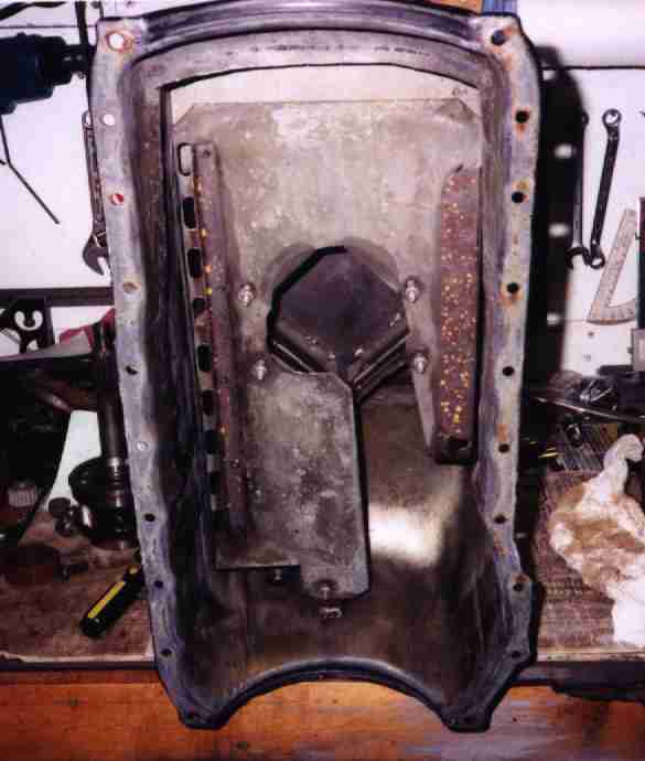 Mike had modified his pan similar to the factory Pantera GTS pan, with a full
length sump. Mike added a stripper and a bunch of baffling, which is not
present in the factory pan.
Mike had modified his pan similar to the factory Pantera GTS pan, with a full
length sump. Mike added a stripper and a bunch of baffling, which is not
present in the factory pan.
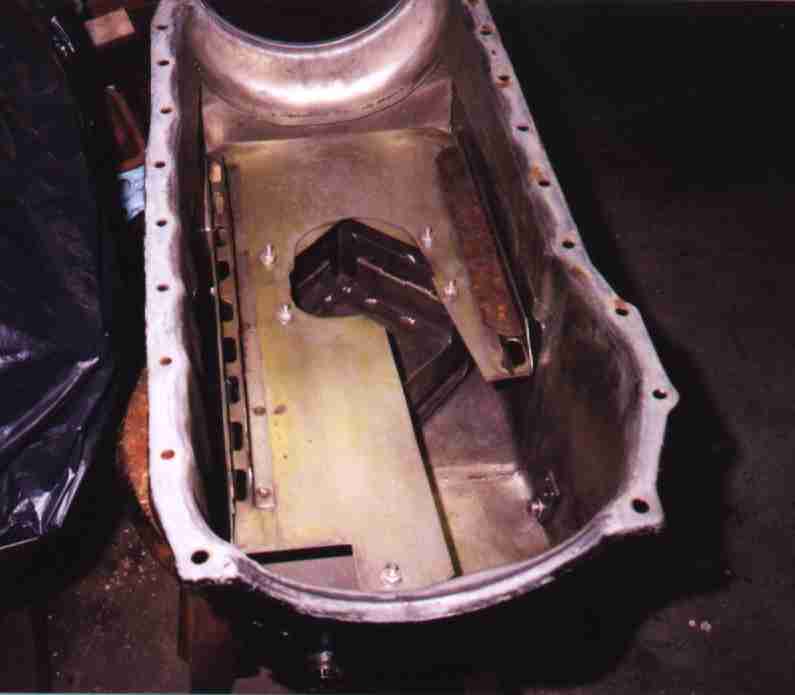 Here it is cleaned up some, at a different angle.
 Mike made an extended pickup and welded a support bracket.
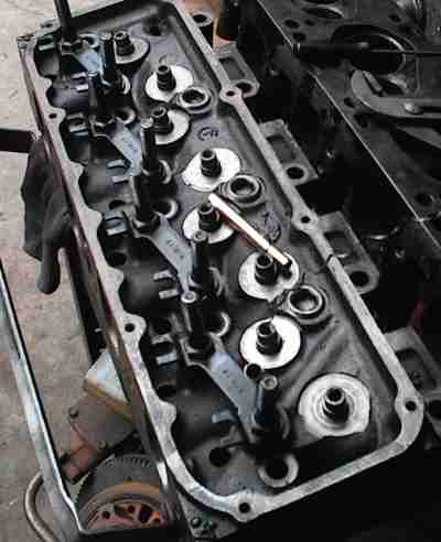
 The engine had a big roller cam in its previous life, with appropriate
gigondamundo 600 pound valve springs, 1.625" in diameter. The spring seats
had been machined a quarter inch or so down to make room for the taller
springs and hardened cup type seats. The new 350 pound springs were shorter,
and stock 1.44" diameter. There was now nothing to locate them on the heads,
and nobody made a spring seat with the right size guide hole and spring pocket
diameter.
The engine had a big roller cam in its previous life, with appropriate
gigondamundo 600 pound valve springs, 1.625" in diameter. The spring seats
had been machined a quarter inch or so down to make room for the taller
springs and hardened cup type seats. The new 350 pound springs were shorter,
and stock 1.44" diameter. There was now nothing to locate them on the heads,
and nobody made a spring seat with the right size guide hole and spring pocket
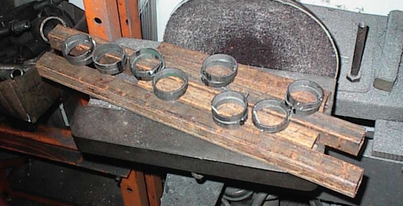
diameter.After a bunch of measuring, I obtained some expensive 1018 steel tubing, which looked just like muffler pipe, except for a slightly different wall thickness. I sawed off a bunch of short rings.
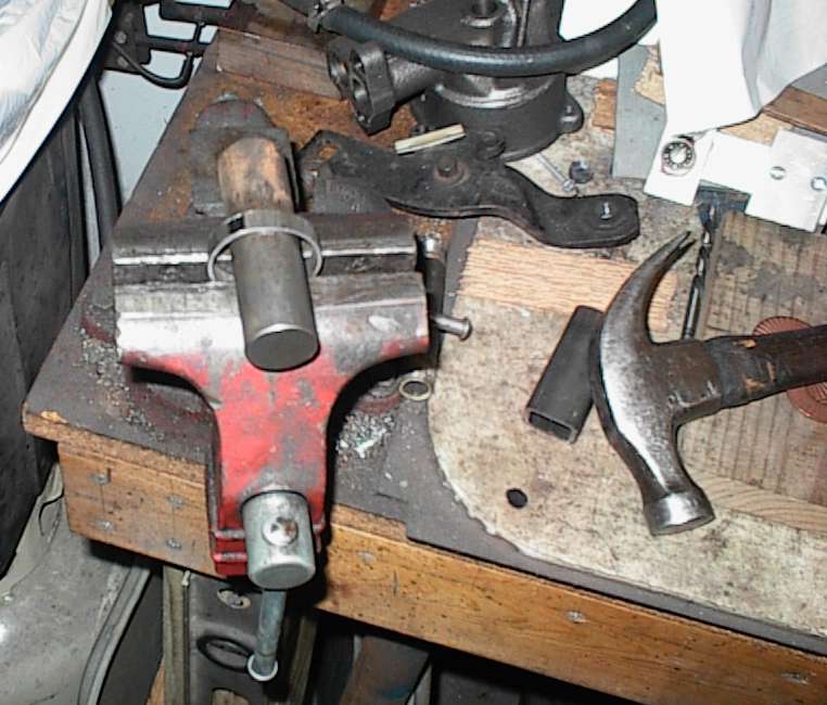 The rings were slightly too small; they bound on the springs and were a loose
fit in the cups. I expanded them by hammering gently over a round bar, until
they were a tight snap fit into the spring cups.
The rings were slightly too small; they bound on the springs and were a loose
fit in the cups. I expanded them by hammering gently over a round bar, until
they were a tight snap fit into the spring cups.
I tack welded the rings to to the cups, then soldered them in place. I have pictures of this somewhere. A stack of ordinary valve spring shims went inside the extended cups, which were plenty tall enough to keep the springs in place.
If there had been cups available in the right configuration, I would have simply purchased them. I even checked to see if anyone made a 1.625" spring with the right rate, but nothing was even close. Once you cut the heads for monster springs, nobody ever assumes you'll go back to smaller ones, so I wound up having to modify the 1.625" cups.
They look tacky in the assembled heads, but they work.
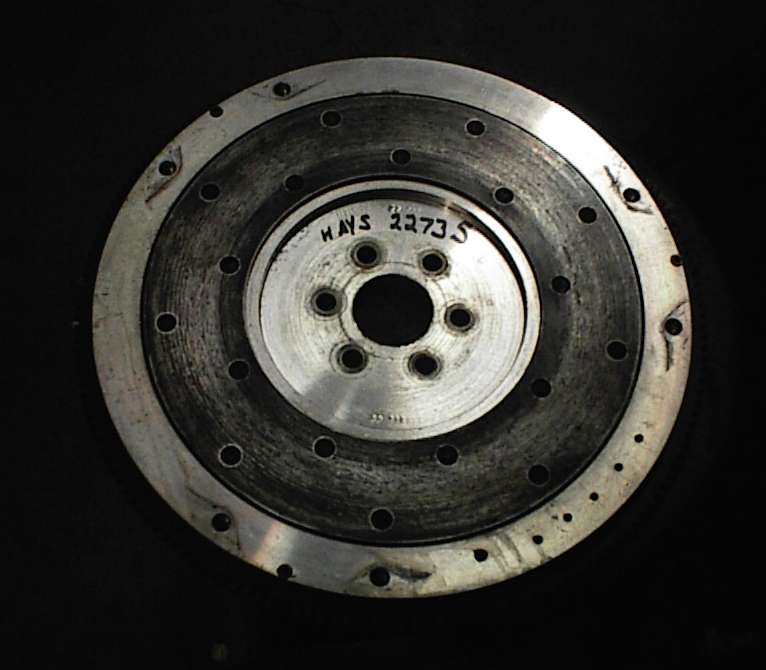 Front side of flywheel. These suckers are close to $400 nowadays!
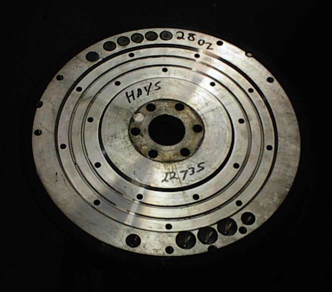 Back side of flywheel. Holes are for balancing.
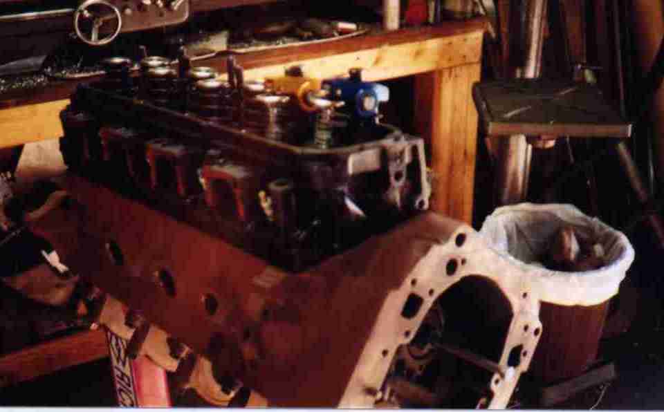
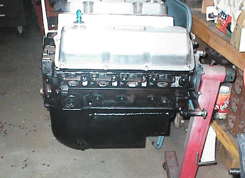 Of course I managed to get flare from the flash this time. (sigh) Note the
shape of the oil pan.
Of course I managed to get flare from the flash this time. (sigh) Note the
shape of the oil pan.
 AN fittings in the valve covers are part of Mike's crankcase evacuation
system. Ready to wrap in plastic now...
AN fittings in the valve covers are part of Mike's crankcase evacuation
system. Ready to wrap in plastic now...