I'm still finding pictures here and there, so I'll update the page from time to time. Yes, it really has been eight years that I've been looking for round tuits...
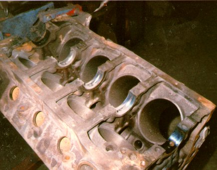 289 block used in the build. The main webs are being slotted to oil the
entire top half of the main bearings, which have extra holes drilled in
them to allow more oil to get to the crank.
289 block used in the build. The main webs are being slotted to oil the
entire top half of the main bearings, which have extra holes drilled in
them to allow more oil to get to the crank.
I thought this one up myself. It turned out the old Chevy Power manual from
GM recommended it, and lots of modern engines come that way from the factory.
Well, at least I was on the right track...
Rotating and Reciprocating Assemblies...
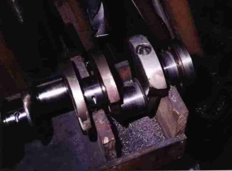
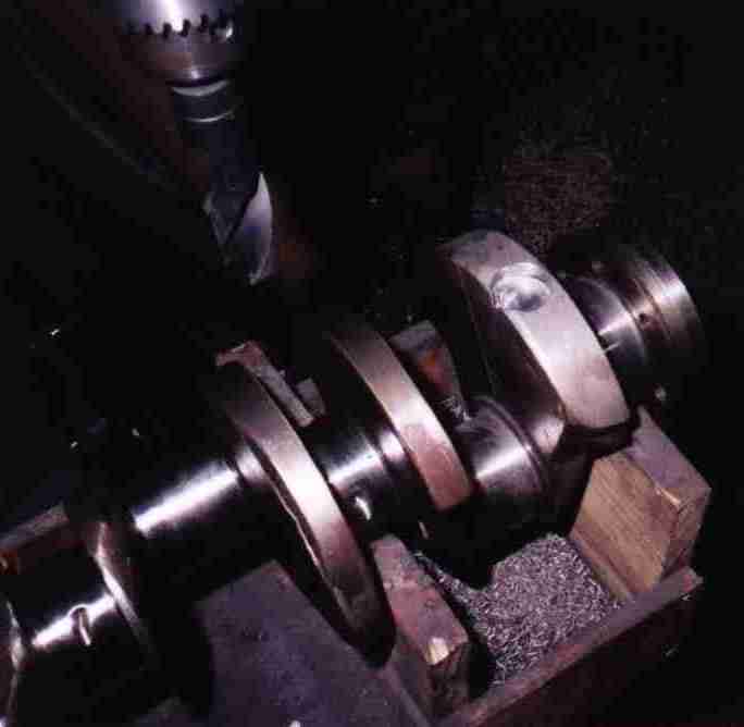
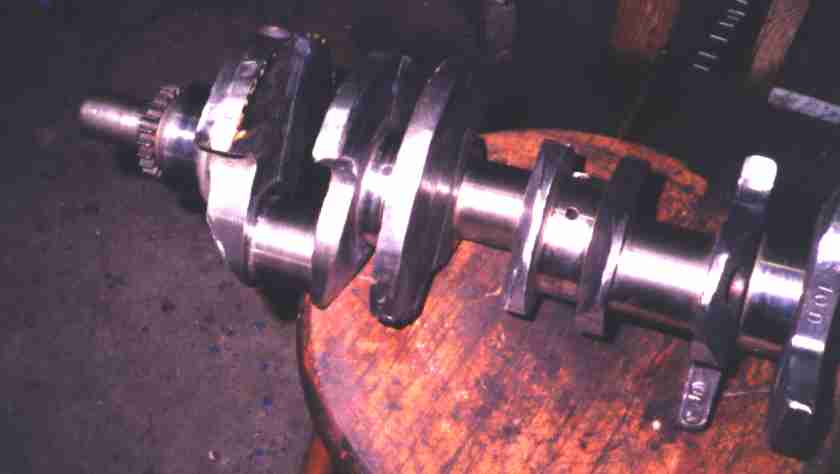
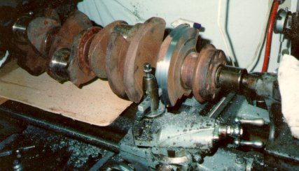 Ordinary 28oz 302 crankshaft. The first step was to turn the counterweights
down round to reduce weight and windage. Then it got radiused and polished
before being ground to large journal Chevy size on the rod throws. Somehow I
failed to take pictures of all this...
Ordinary 28oz 302 crankshaft. The first step was to turn the counterweights
down round to reduce weight and windage. Then it got radiused and polished
before being ground to large journal Chevy size on the rod throws. Somehow I
failed to take pictures of all this...
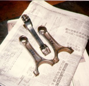
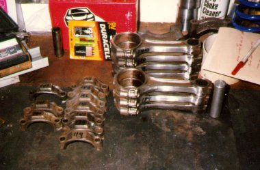 5.56" Chevy 400 small block rods, lightened and polished. They're a half inch
longer than the stock 302 rods. These haven't been narrowed to fit the Ford
crank yet.
5.56" Chevy 400 small block rods, lightened and polished. They're a half inch
longer than the stock 302 rods. These haven't been narrowed to fit the Ford
crank yet.
 Matching individual rod shanks and caps by weight. It took ten shanks and
twelve caps to make eight matched rods; some combinations did not line up well
enough for the rods to be resized.
Matching individual rod shanks and caps by weight. It took ten shanks and
twelve caps to make eight matched rods; some combinations did not line up well
enough for the rods to be resized.
Nowadays I'd just collect more rods until I matched up eight that were the way
I wanted.
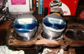 Keith Black hypereutectic pistons, 1.14" pin height. They're for a 6" rod 383
Chevy. The domes have to be reprofiled to fit Ford combustion chambers. I
used a safe-edge file and a lot of time; next time I'll build a fixture and
use a router.
Keith Black hypereutectic pistons, 1.14" pin height. They're for a 6" rod 383
Chevy. The domes have to be reprofiled to fit Ford combustion chambers. I
used a safe-edge file and a lot of time; next time I'll build a fixture and
use a router.
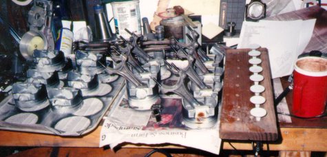 Parts have been coated, ready for baking. There's more here than just TRX; I
usually batch coating jobs if I can.
Parts have been coated, ready for baking. There's more here than just TRX; I
usually batch coating jobs if I can.
Balancing...
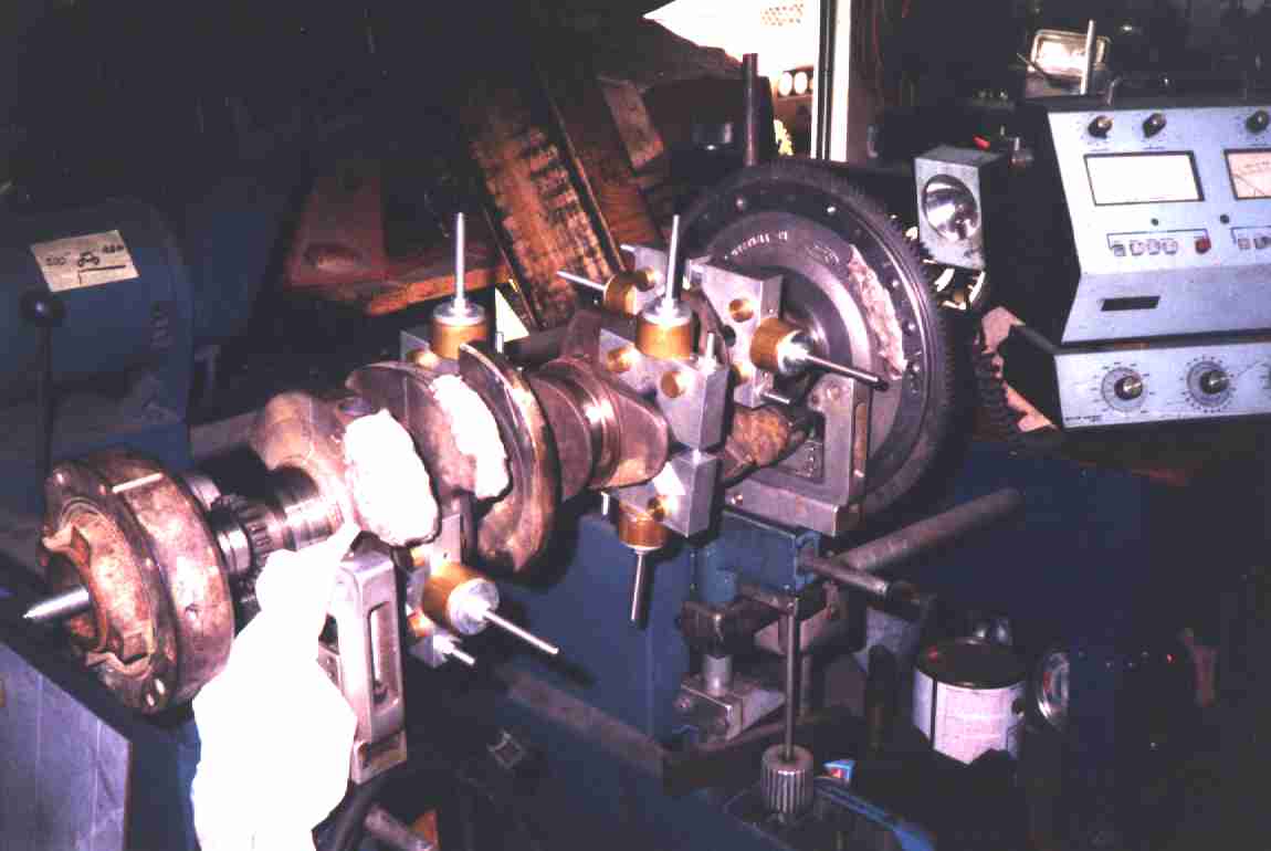 This is the rotating assembly. It was already balanced by Crankshaft
Specialist in Memphis. See the huge wads of modeling clay on the
counterweights? That's why I now own my own balancing machine.
This is the rotating assembly. It was already balanced by Crankshaft
Specialist in Memphis. See the huge wads of modeling clay on the
counterweights? That's why I now own my own balancing machine.
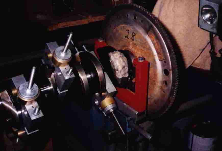 Here's the other end. The assclowns in Memphis weren't even in the ballpark,
much less close. It took several ounces of lead fill to bring this thing into
balance.
Here's the other end. The assclowns in Memphis weren't even in the ballpark,
much less close. It took several ounces of lead fill to bring this thing into
balance.
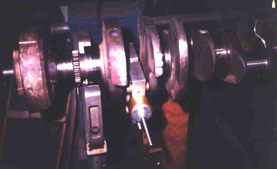
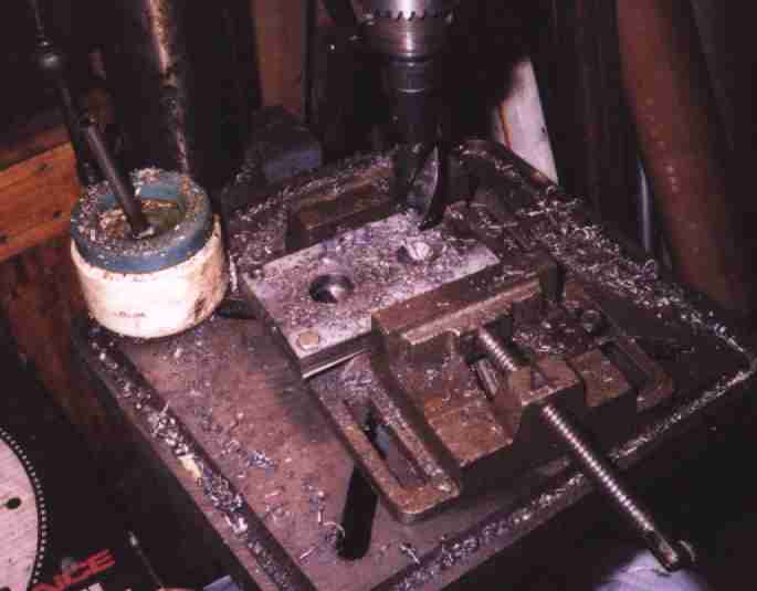
 The balance machine said more weight was needed here. The first step
is to drill out some iron to make room for something heavier.
The balance machine said more weight was needed here. The first step
is to drill out some iron to make room for something heavier.
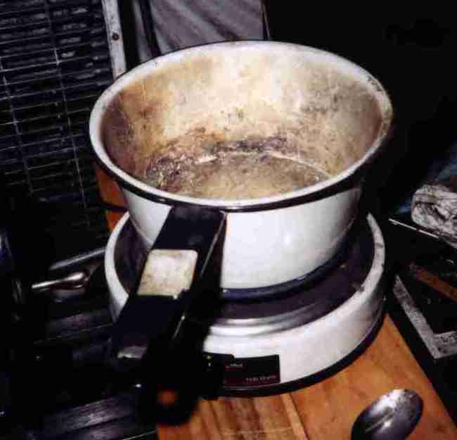 One pot of molten lead. It's not as dense as "Mallory metal" (a tungsten
alloy) but it's a whole lot cheaper - almost free, vs. up to $20 per piece for
Mallory. Most balance jobs will come out with just lead; you usually know
when you first spin it up if you'll need Mallory or if lead will do. I use old
wheelweights from a local tire store.
One pot of molten lead. It's not as dense as "Mallory metal" (a tungsten
alloy) but it's a whole lot cheaper - almost free, vs. up to $20 per piece for
Mallory. Most balance jobs will come out with just lead; you usually know
when you first spin it up if you'll need Mallory or if lead will do. I use old
wheelweights from a local tire store.
 Lead poured in, tamped flat with a drift, ready for steel plug to be welded
over. The crank took two 1" fills in back and two in front, with a three
additional 1/2" in front.
Lead poured in, tamped flat with a drift, ready for steel plug to be welded
over. The crank took two 1" fills in back and two in front, with a three
additional 1/2" in front.
 There's lead in the front counterweight. It wasn't enough, so more went in
the second counterweight. Steel plugs are welded over the holes; these
haven't been ground flush yet. It gets spun again to see how close it is
before detailing will begin. After everything is welded, ground, and
smoothed, it gets a last spin.
There's lead in the front counterweight. It wasn't enough, so more went in
the second counterweight. Steel plugs are welded over the holes; these
haven't been ground flush yet. It gets spun again to see how close it is
before detailing will begin. After everything is welded, ground, and
smoothed, it gets a last spin.
 The finished crank; lightened, balanced, and polished. You can't see it well
in this picture, but there are 5/8" long lead-in slots ground ahead of the oil
holes on the mains, and all the corners in the oilways were radiused with a
Dremel with a long ball-end bit.
The finished crank; lightened, balanced, and polished. You can't see it well
in this picture, but there are 5/8" long lead-in slots ground ahead of the oil
holes on the mains, and all the corners in the oilways were radiused with a
Dremel with a long ball-end bit.
Oiling...
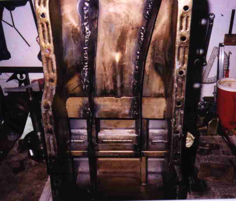 Milodon T-sump pan I got from Millam Tackitt. I traded him a Cadillac engine
for it. I cut .040" steel strips and welded them in canted against the
direction of crank rotation to catch and divert oil thrown off the crank.
Milodon T-sump pan I got from Millam Tackitt. I traded him a Cadillac engine
for it. I cut .040" steel strips and welded them in canted against the
direction of crank rotation to catch and divert oil thrown off the crank.
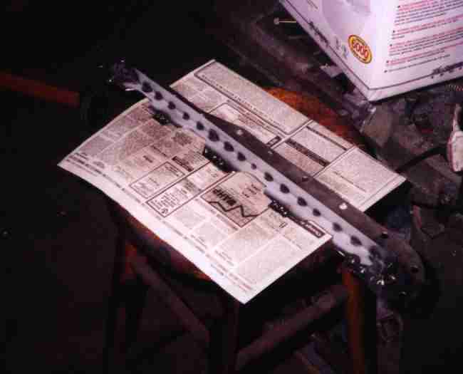
 .040" steel crank scraper. Notice how much wider it is than a Chevy scraper;
lots of room in a Ford crankcase. This one's wider than an ordinary Ford one
would be since the counterweights on the crank were turned down.
.040" steel crank scraper. Notice how much wider it is than a Chevy scraper;
lots of room in a Ford crankcase. This one's wider than an ordinary Ford one
would be since the counterweights on the crank were turned down.
 As the oil is scraped off, it's directed right to the oil pan gasket. I
figured this would not necessarily be a good thing, so I made a secondary
deflector to keep it from impinging directly on the gasket.
As the oil is scraped off, it's directed right to the oil pan gasket. I
figured this would not necessarily be a good thing, so I made a secondary
deflector to keep it from impinging directly on the gasket.
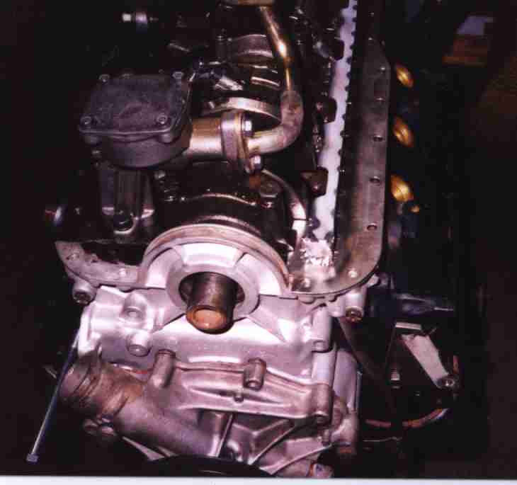 Finished scraper in place. Note heated and bent oil pickup tube; the high
volume pump is longer and puts the tube in a different spot where it will hit
the bottom of the pan, so it has to be modified.
Finished scraper in place. Note heated and bent oil pickup tube; the high
volume pump is longer and puts the tube in a different spot where it will hit
the bottom of the pan, so it has to be modified.
Cylinder Heads...
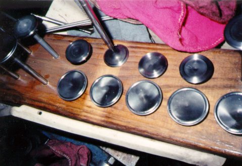 Manley one-piece valves were reworked on the lathe. The fronts of the intakes
were grooved to reduce reversion at low lift. Same with the backs of the
exhaust valves, though you can't see it in this shot. Fronts of the exhaust
valves were radiused. Then they got sandblasted and ceramic coated.
Manley one-piece valves were reworked on the lathe. The fronts of the intakes
were grooved to reduce reversion at low lift. Same with the backs of the
exhaust valves, though you can't see it in this shot. Fronts of the exhaust
valves were radiused. Then they got sandblasted and ceramic coated.
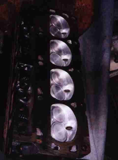 Combustion chambers were polished shiny, then sandblasted and ceramic coated.
The heads were milled .060", extensively ported on the exhaust side, and
pocket ported on the intake side. The combustion chambers have also been
flattened and laid back at the valve seats to unshroud the valves at low lift.
It's not a super-duper-race porting job, but it'll do.
Combustion chambers were polished shiny, then sandblasted and ceramic coated.
The heads were milled .060", extensively ported on the exhaust side, and
pocket ported on the intake side. The combustion chambers have also been
flattened and laid back at the valve seats to unshroud the valves at low lift.
It's not a super-duper-race porting job, but it'll do.
 Exhaust ports were coated too. You can see some of the reshaping work here.
 Cheap stud girdles wouldn't fit under the valve covers. I can't remember
where I ordered them from, now. They had to have recesses carved and corners
rounded; when they came in, they were just straight bars of aluminum.
Cheap stud girdles wouldn't fit under the valve covers. I can't remember
where I ordered them from, now. They had to have recesses carved and corners
rounded; when they came in, they were just straight bars of aluminum.
Induction System...
 Hilborn fuel injection. It is a brand new 1972 manufacture unit; the
original owner died before he installed it. I had originally planned to just
use the manifold and convert to EFI, but I'm going to use the original
mechanical system with a "de-jector" valve plumbed into the fuel bypass to
control mixture. The de-jector is a 55# fuel injector in parallel with the
Hilborn's bypass pill. It is driven by a BASIC Stamp microcontroller and an
ordinary O2 sensor. At part throttle it keeps the engine at stoichiometric
using the O2 for feedback, leaning out the rich Hilborn midrange as needed.
At full throttle a sealed Cherry switch tells the Stamp to stop de-jecting and
let the main pill control the WOT mixture. I'll put up a page about that as I
make more progress, along with details on the airbox, etc.
Hilborn fuel injection. It is a brand new 1972 manufacture unit; the
original owner died before he installed it. I had originally planned to just
use the manifold and convert to EFI, but I'm going to use the original
mechanical system with a "de-jector" valve plumbed into the fuel bypass to
control mixture. The de-jector is a 55# fuel injector in parallel with the
Hilborn's bypass pill. It is driven by a BASIC Stamp microcontroller and an
ordinary O2 sensor. At part throttle it keeps the engine at stoichiometric
using the O2 for feedback, leaning out the rich Hilborn midrange as needed.
At full throttle a sealed Cherry switch tells the Stamp to stop de-jecting and
let the main pill control the WOT mixture. I'll put up a page about that as I
make more progress, along with details on the airbox, etc.
 The Hilborn won't be entirely satisfactory on the street even with the active
fuel control; the injector nozzles are vented to atmosphere, for example, and
you'll always smell gas after you shut the car off. And starting will always
require cranking a bit. The Hilborn's fuel lines loop up over the injectors,
and when you shut the engine off the fuel runs down into the ports, flooding
the motor. So I'll be adding a "turbo timer" doohickey that will let the
engine run a few seconds after turning off the key and closing the fuel
solenoid. That will use up most of the fuel in the lines. Crude, but hey,
it's a prehistoric system never intended for street use; you have to put up
with "features".
The Hilborn won't be entirely satisfactory on the street even with the active
fuel control; the injector nozzles are vented to atmosphere, for example, and
you'll always smell gas after you shut the car off. And starting will always
require cranking a bit. The Hilborn's fuel lines loop up over the injectors,
and when you shut the engine off the fuel runs down into the ports, flooding
the motor. So I'll be adding a "turbo timer" doohickey that will let the
engine run a few seconds after turning off the key and closing the fuel
solenoid. That will use up most of the fuel in the lines. Crude, but hey,
it's a prehistoric system never intended for street use; you have to put up
with "features".
 The long stacks won't be used, of course. The new stacks are only 2.5" tall
to allow adequate clearance inside the airbox, and clearance between the
airbox and hood. There is also a distributor fangle involved - the airbox
won't clear the distributor cap. So... get rid of the cap. My buddy Doug
Glosson has worked up a nifty deal to use four optical pickups mounted to the
distributor breaker plate, each one driving a single two-lead GM coil pack.
Four coil packs, eight plugs. It will look like a distributorless system, but
it'll actually be a hybrid, sort of like the 'de-jected' Hilborn.
The long stacks won't be used, of course. The new stacks are only 2.5" tall
to allow adequate clearance inside the airbox, and clearance between the
airbox and hood. There is also a distributor fangle involved - the airbox
won't clear the distributor cap. So... get rid of the cap. My buddy Doug
Glosson has worked up a nifty deal to use four optical pickups mounted to the
distributor breaker plate, each one driving a single two-lead GM coil pack.
Four coil packs, eight plugs. It will look like a distributorless system, but
it'll actually be a hybrid, sort of like the 'de-jected' Hilborn.
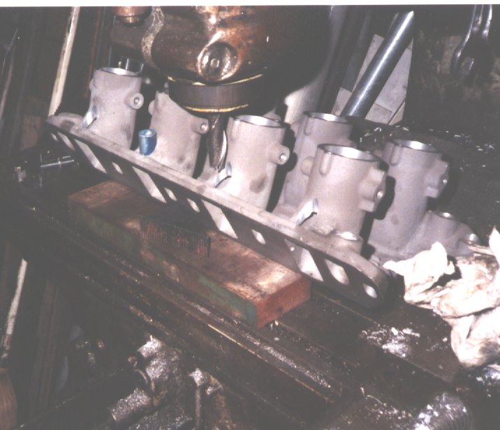
 Since the original dead 302 was still in the RX7, I dropped the Hilborn in
place to make a clearance test.
Since the original dead 302 was still in the RX7, I dropped the Hilborn in
place to make a clearance test.
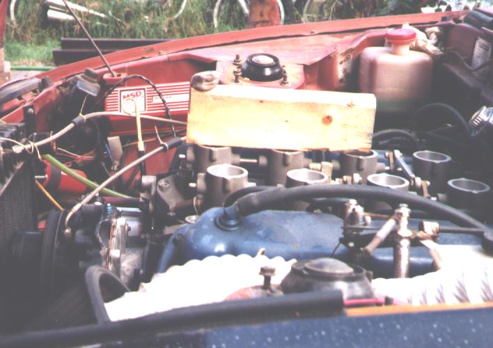 Knot of clay on top of 2x4 shows the clearance. Allowing room for the engine
to move on its mounts, I have 4" at the front for the airbox. The RX hood
slopes down sharply at the front, and the 302 slants shallowly to the back, so
there's all kinds of clearance back by the firewall.
Knot of clay on top of 2x4 shows the clearance. Allowing room for the engine
to move on its mounts, I have 4" at the front for the airbox. The RX hood
slopes down sharply at the front, and the 302 slants shallowly to the back, so
there's all kinds of clearance back by the firewall.
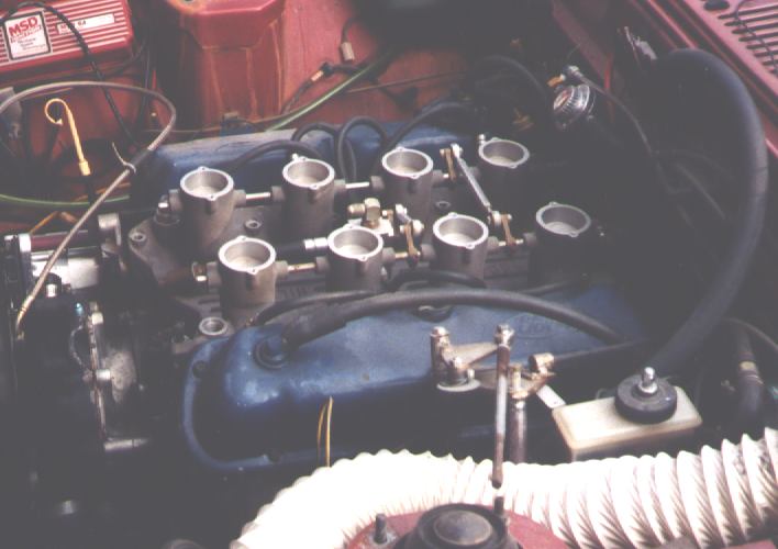
 Expensive Hilborn intake has a date with the milling machine. I canted the
injector bungs to clear the valve covers on one side and the airbox adapters
on the other.
Expensive Hilborn intake has a date with the milling machine. I canted the
injector bungs to clear the valve covers on one side and the airbox adapters
on the other.
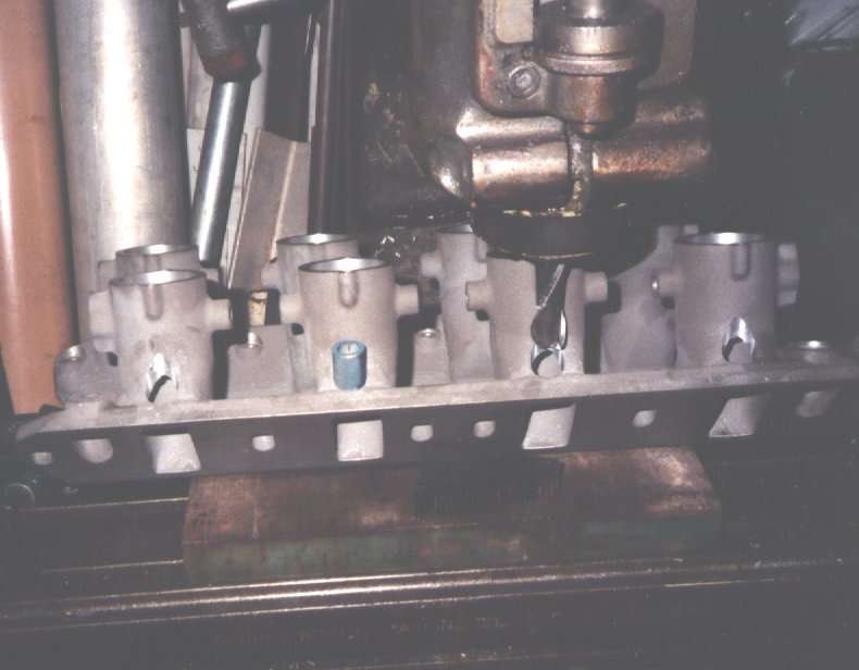 The bungs are centered in the ports; it's just the angle of the shot
that makes them look offset.
The bungs are centered in the ports; it's just the angle of the shot
that makes them look offset.
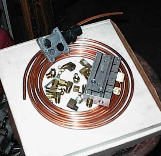 GM IAC for the 7730 ECM, vacuum distribution block, copper tubing, and a bunch
of fittings. Vacuum is collected and averaged from all eight intake ports,
below the Hilborn butterflies, for the MAP sensor, power brake booster, and
Idle Air Control.
GM IAC for the 7730 ECM, vacuum distribution block, copper tubing, and a bunch
of fittings. Vacuum is collected and averaged from all eight intake ports,
below the Hilborn butterflies, for the MAP sensor, power brake booster, and
Idle Air Control.
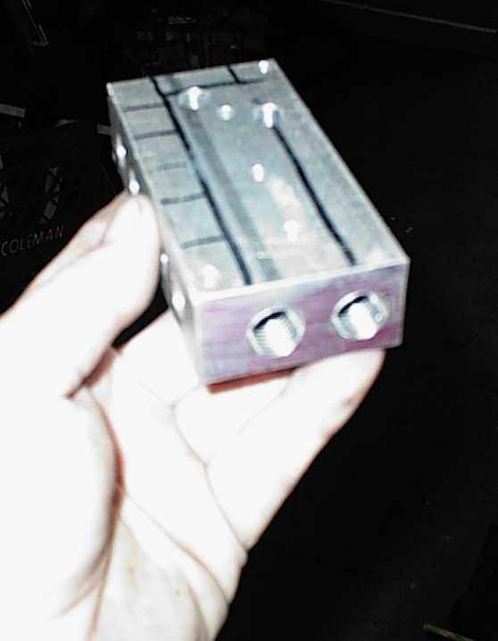 Distribution block bolts up against bottom of intake. The IAC is mounted on
top, with holes through the intake to pass air from one to the other. I just
grabbed the first chunk of aluminum I found; later I scoped out some much
cleaner solutions, but by then I'd finished the first one.
Distribution block bolts up against bottom of intake. The IAC is mounted on
top, with holes through the intake to pass air from one to the other. I just
grabbed the first chunk of aluminum I found; later I scoped out some much
cleaner solutions, but by then I'd finished the first one.
 Compression fittings on bottom of intake. I drilled and tapped 1/4 NPT,
screwed them in with epoxy, then epoxied around the hexes.
Compression fittings on bottom of intake. I drilled and tapped 1/4 NPT,
screwed them in with epoxy, then epoxied around the hexes.
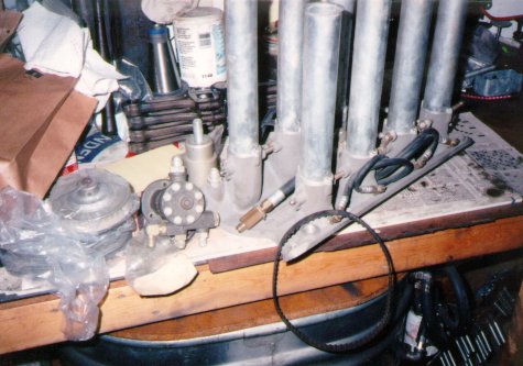
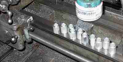 Saw up a bunch of 3/4" aluminum tubing...
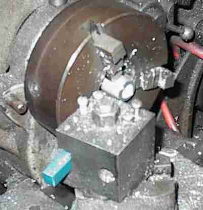 Face to length, chamfer the outside ends, radius with deburr tool, then bore
to size with boring bar.
Face to length, chamfer the outside ends, radius with deburr tool, then bore
to size with boring bar.
 I fired up the MIG welder, but the heavy aluminum casting and thinwall tubes
were beyond my skill. Even preheating with a propane torch, I vaporized a lot
of wire.
I fired up the MIG welder, but the heavy aluminum casting and thinwall tubes
were beyond my skill. Even preheating with a propane torch, I vaporized a lot
of wire.
 Once it became apparent that the bungs were firmly attached, even if not
airtight, I ground the globby aluminum worms into some semblance of neatness,
cleaned everything again, and used epoxy to seal everything up.
Once it became apparent that the bungs were firmly attached, even if not
airtight, I ground the globby aluminum worms into some semblance of neatness,
cleaned everything again, and used epoxy to seal everything up.
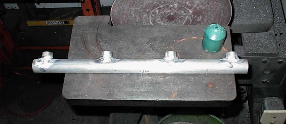 After the manifold bungs were welded in, I marked off the corresponding bung
holes in the fuel rails. I used 1" 6061 tubing for the rails, with the bungs
MIGged and aluminum soldered in place. I don't have the trick with the solder
at all, unfortunately. But they won't leak, anyway.
After the manifold bungs were welded in, I marked off the corresponding bung
holes in the fuel rails. I used 1" 6061 tubing for the rails, with the bungs
MIGged and aluminum soldered in place. I don't have the trick with the solder
at all, unfortunately. But they won't leak, anyway.
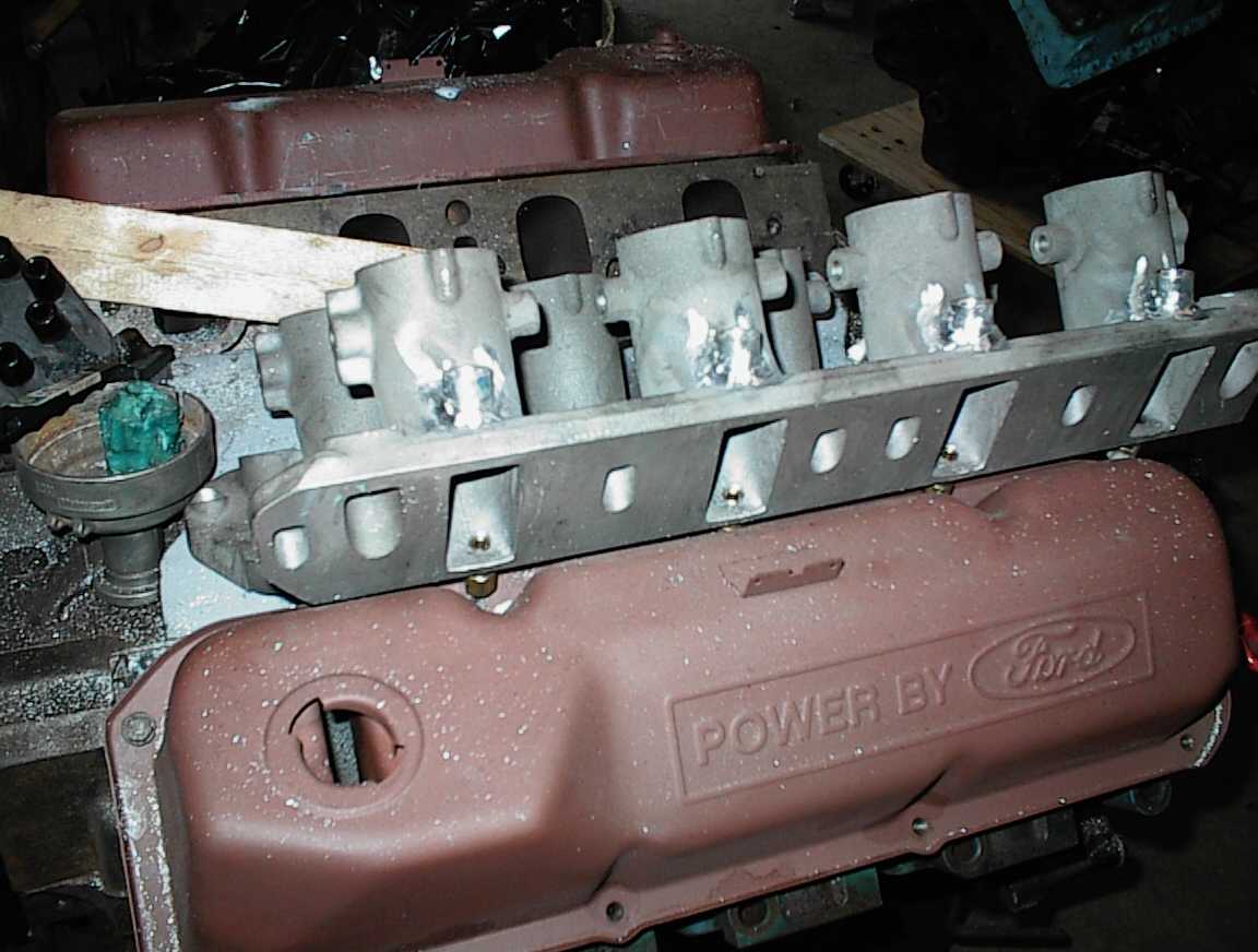
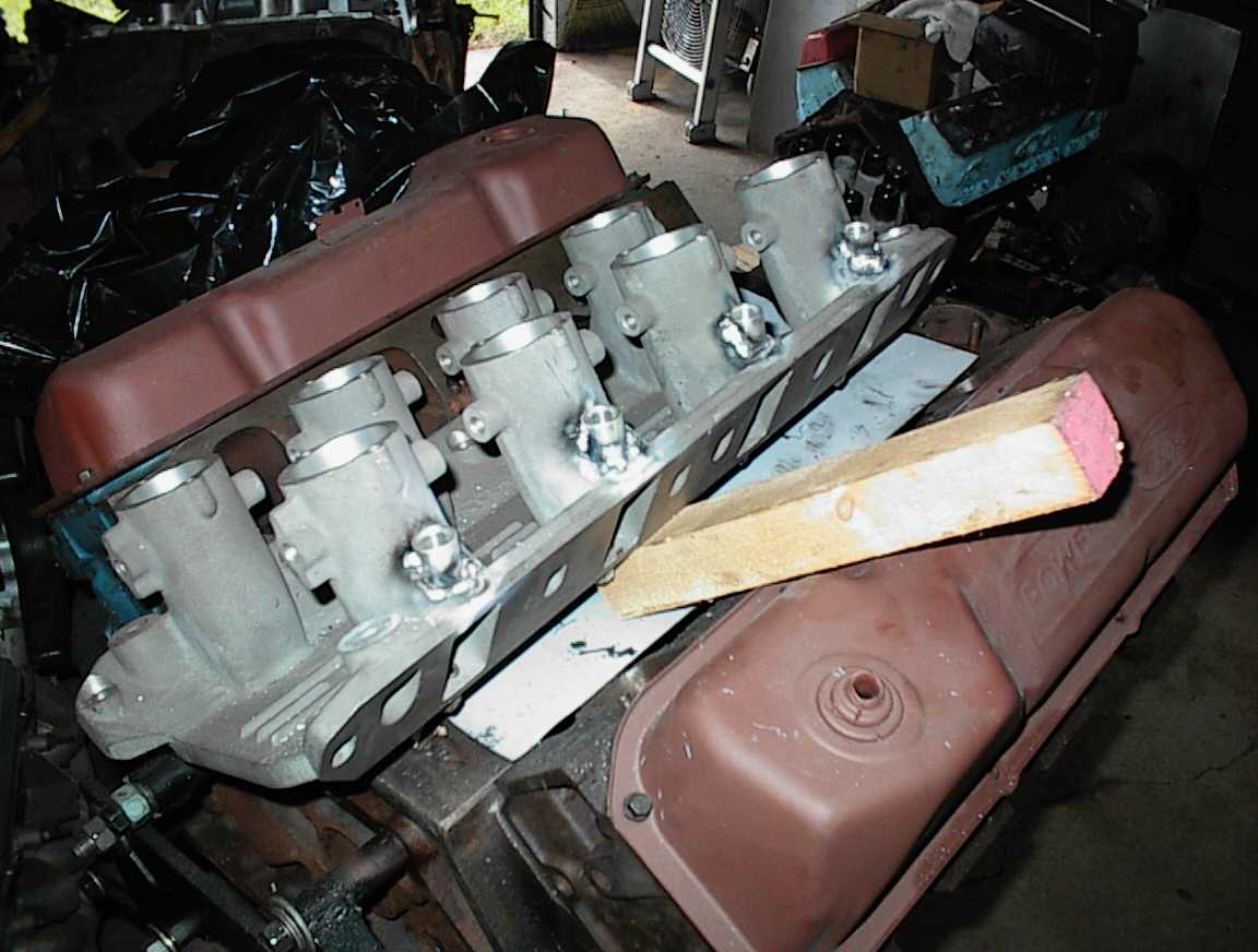
 Intake base. Aluminum plates on the bottom are drilled and countersunk to
bolt to the original stack mounting holes. Steel plates bolt to the aluminum
plates. The original purpose of all this was to do a long tube crossram
setup, with plenums crossing over each valve cover. I finally decided it was
more time and money than I wanted to get into, so I'm just building an
aluminum airbox to bolt on top.
Intake base. Aluminum plates on the bottom are drilled and countersunk to
bolt to the original stack mounting holes. Steel plates bolt to the aluminum
plates. The original purpose of all this was to do a long tube crossram
setup, with plenums crossing over each valve cover. I finally decided it was
more time and money than I wanted to get into, so I'm just building an
aluminum airbox to bolt on top.
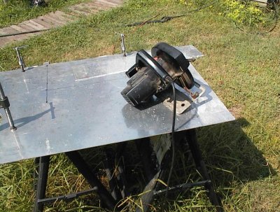 Carbide blade on the circular saw makes short work of 1/8" aluminum plate.
Assembly...
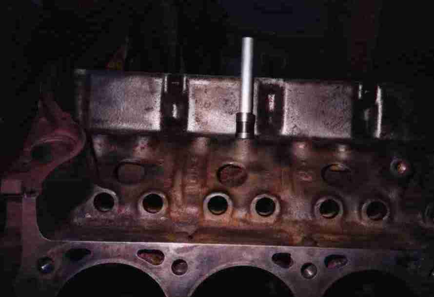
 Checking the deck height. After having the block milled, the pistons are
.003-.005" proud of the deck.
Checking the deck height. After having the block milled, the pistons are
.003-.005" proud of the deck.
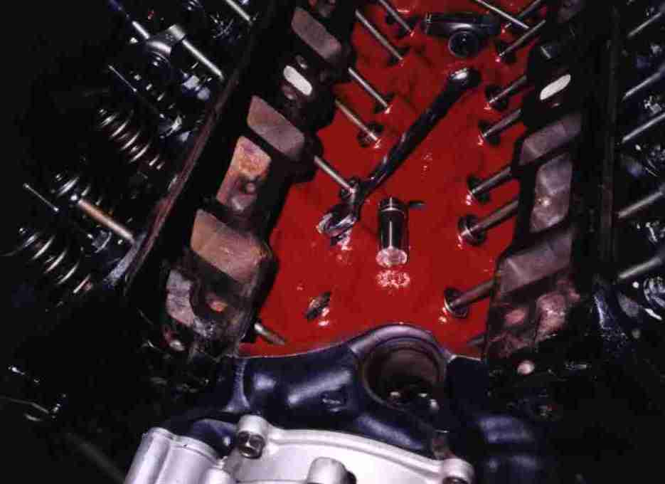 A couple of lifters didn't want to go in when I was putting it together for
the last time. There were burrs on the bottoms of their bores, it happens
sometimes if someone got stupid beating the lifters out on disassembly.
I made this tool from an old lifter. Pack the grooves with grease to catch
the shavings, turn with a wrench. I really didn't want to pull the thing back
apart again.
A couple of lifters didn't want to go in when I was putting it together for
the last time. There were burrs on the bottoms of their bores, it happens
sometimes if someone got stupid beating the lifters out on disassembly.
I made this tool from an old lifter. Pack the grooves with grease to catch
the shavings, turn with a wrench. I really didn't want to pull the thing back
apart again.
 I also made this handy gage tool while I was at it. An old lifter epoxied to
a piece of aluminum rod; now I just pop it into each hole to make sure
everything is okay before beginning assembly.
I also made this handy gage tool while I was at it. An old lifter epoxied to
a piece of aluminum rod; now I just pop it into each hole to make sure
everything is okay before beginning assembly.
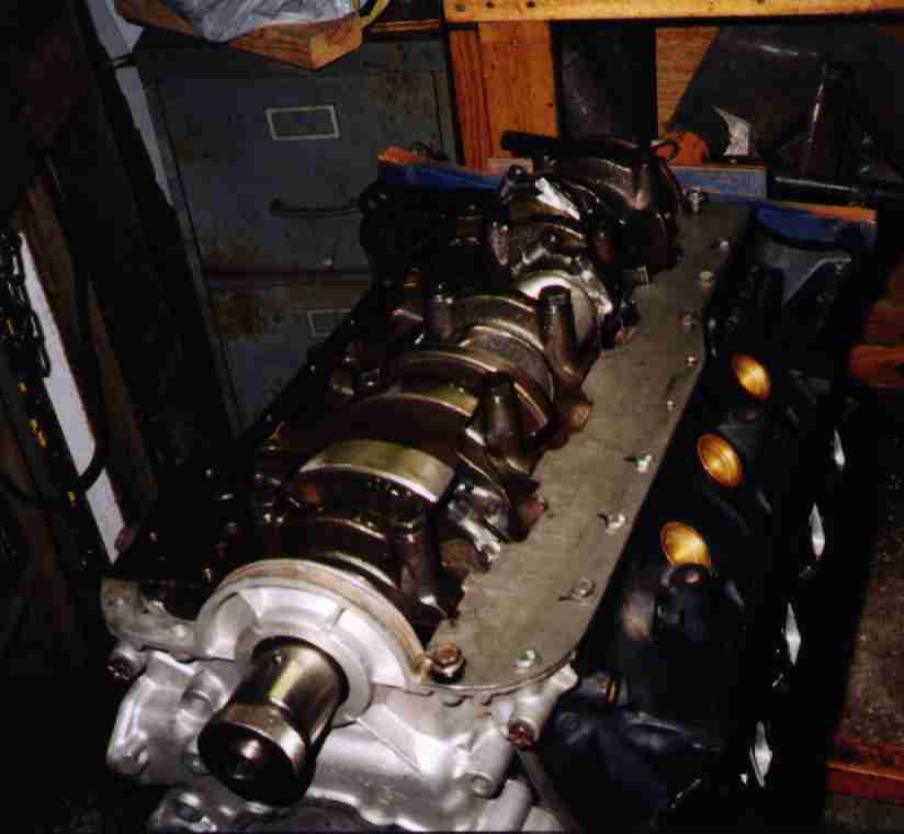
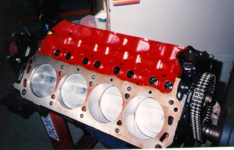 Assembled short block. Paint is red Rust-Oleum. You'll see paint/no-paint in
the pictures; there were several trial fits.
Assembled short block. Paint is red Rust-Oleum. You'll see paint/no-paint in
the pictures; there were several trial fits.
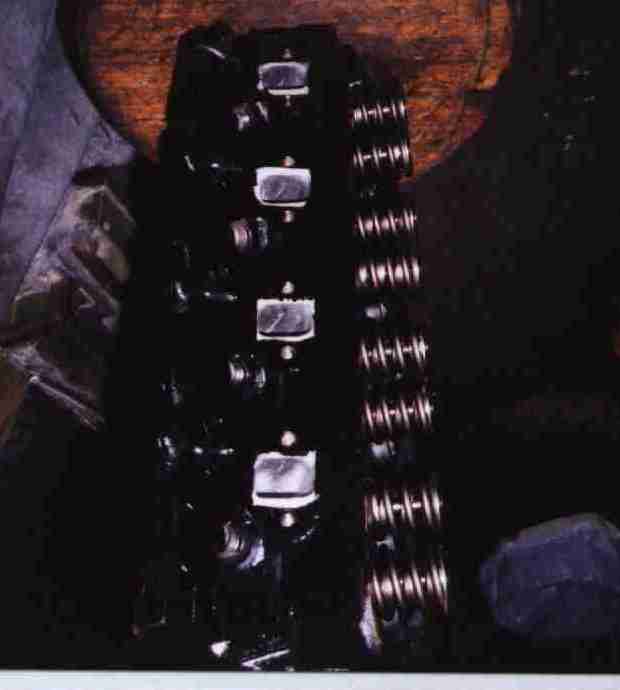
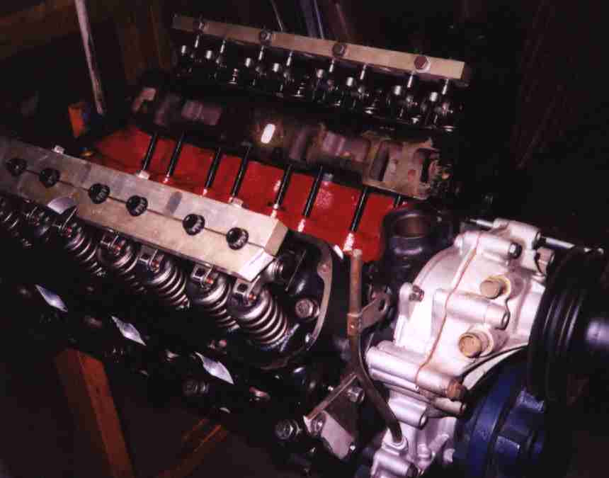 Crane titanium retainers, Competition Cams steel roller rockers, Sig Erson
300# springs from the cam kit, 7/16" studs, stud girdle, custom TFS hardened
pushrods. Rocker valleys have been sandblasted and coated with Tech Line "oil
shedding" stuff to help oil drain back faster. I don't know if it works, but
it's fancier than Rust-Oleum...
Crane titanium retainers, Competition Cams steel roller rockers, Sig Erson
300# springs from the cam kit, 7/16" studs, stud girdle, custom TFS hardened
pushrods. Rocker valleys have been sandblasted and coated with Tech Line "oil
shedding" stuff to help oil drain back faster. I don't know if it works, but
it's fancier than Rust-Oleum...
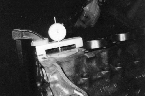
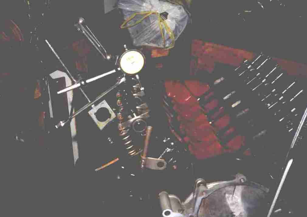 Plate bolts to valve cover holes, provides base for magnetic dial indicator.
Setting the hydraulic lifters to .030" preload.
Plate bolts to valve cover holes, provides base for magnetic dial indicator.
Setting the hydraulic lifters to .030" preload.
Accessories...
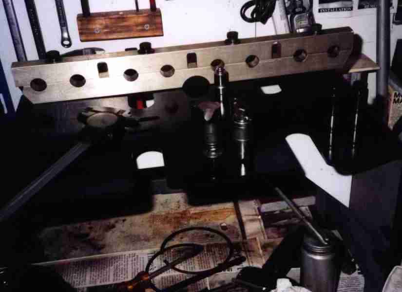
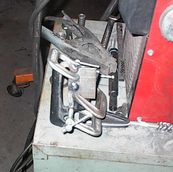
 This is a pair of 5/16" steel plates for the new tri-Y headers. I've already
drilled, tapped, and countersunk and bolted two pieces together. The next
step is to bore the holes to size on the lathe.
This is a pair of 5/16" steel plates for the new tri-Y headers. I've already
drilled, tapped, and countersunk and bolted two pieces together. The next
step is to bore the holes to size on the lathe.
There are two of these plates, to attach the Ys to the collectors.
 My fancy modified timing cover. I cut a hole to put an oil filler tube in
like an old 221 or 260.
My fancy modified timing cover. I cut a hole to put an oil filler tube in
like an old 221 or 260.
I needed some more radiator clearance, so I decided to go for it and changed to a short pump from a 2.5 liter Fiero. I used a chunk of 1/2" plate to mount it, then freehand-milled the proper reliefs in the back of the plate to direct water to the ports in the timing cover. I used a boring head to make the counterbore for the pump, drilled and tapped to mount it, etc. I took a lot of pictures, but they were on 35mm, and as happened more than once, the developers lost them.
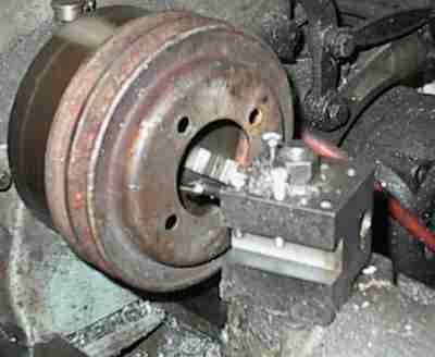 With the short water pump grafted on, the next thing was to find a new lower
pulley. I found this one laying on the ground at a junkyard. I think it's
from an import. The diameter was correct to clear the sway bar, and the
sheaves were close in.
With the short water pump grafted on, the next thing was to find a new lower
pulley. I found this one laying on the ground at a junkyard. I think it's
from an import. The diameter was correct to clear the sway bar, and the
sheaves were close in.
 I chucked the pulley in the lathe and bored out the center hole to match the
lip on the 302's damper.
I chucked the pulley in the lathe and bored out the center hole to match the
lip on the 302's damper.
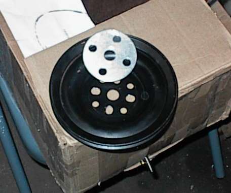
 Here's the pulley and the damper. They're a snug fit.
 With the damper and pulley together, I used a transfer punch to mark where the
new mounting holes had to be. A few passes with the drill and countersink,
and now I have a new lower pulley!
With the damper and pulley together, I used a transfer punch to mark where the
new mounting holes had to be. A few passes with the drill and countersink,
and now I have a new lower pulley!
 The upper pulley is off a '77 Cadillac Eldorado. I had to shim it out 1/8" to
line up with the new lower pulley. The aluminum shim was made on the lathe
and drill press.
The upper pulley is off a '77 Cadillac Eldorado. I had to shim it out 1/8" to
line up with the new lower pulley. The aluminum shim was made on the lathe
and drill press.
 With the pulleys done, I could do the air conditioning compressor. I went to
the junkyard and measured everything they had, and the ordinary GM R-4
compressor is the shortest of them all. It was designed to tuck into the
limited width of FWD engine compartments. First thing I did was to measure
the distance from the lower pulley groove to the front of the right cylinder
head, then weld a threaded bung onto a piece of steel to make a spacer
bracket.
With the pulleys done, I could do the air conditioning compressor. I went to
the junkyard and measured everything they had, and the ordinary GM R-4
compressor is the shortest of them all. It was designed to tuck into the
limited width of FWD engine compartments. First thing I did was to measure
the distance from the lower pulley groove to the front of the right cylinder
head, then weld a threaded bung onto a piece of steel to make a spacer
bracket.
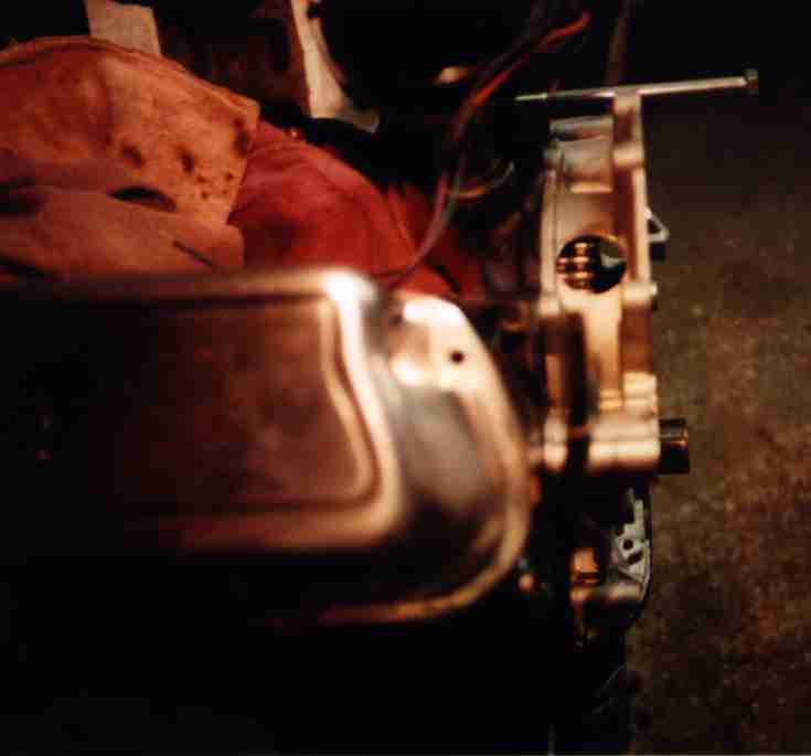
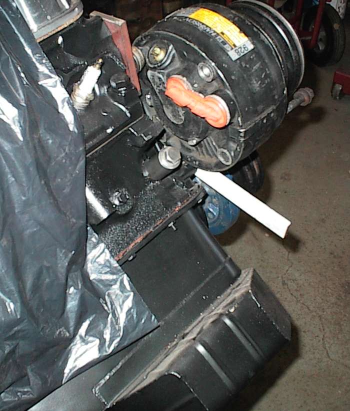 With the spacer on, I could use a bolt to hold the compressor in place to
build the rest of the bracket. The compressor was rotated so the lines would
clear the headers. It's tucked in quite close to the water pump. You can see
the tube bolted to the accessory boss on the block above the pan rail; a tube
was welded to a threaded block that went on the back of the compressor, bolted
through from the front. I thought I took more pictures than this. [sigh]
There will be another bracket from one of the header bolts to an outboard
compressor bolt, to stabilize the compressor.
With the spacer on, I could use a bolt to hold the compressor in place to
build the rest of the bracket. The compressor was rotated so the lines would
clear the headers. It's tucked in quite close to the water pump. You can see
the tube bolted to the accessory boss on the block above the pan rail; a tube
was welded to a threaded block that went on the back of the compressor, bolted
through from the front. I thought I took more pictures than this. [sigh]
There will be another bracket from one of the header bolts to an outboard
compressor bolt, to stabilize the compressor.
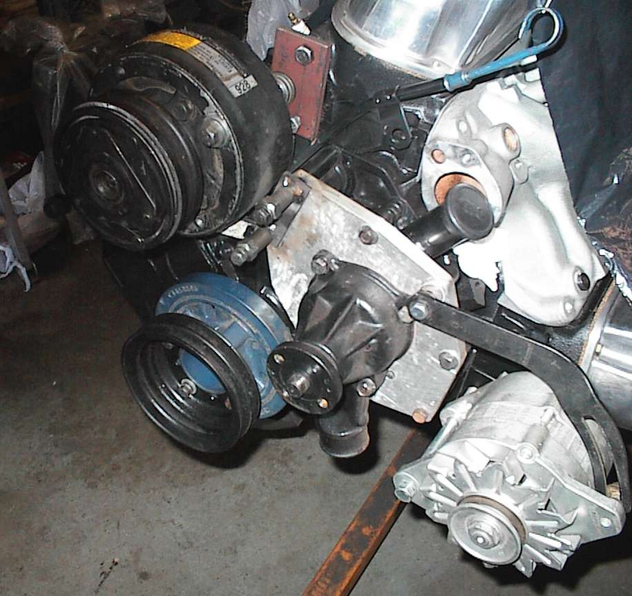 A front shot. I welded up bits of tubing and flat stock to make the front
brackets; I'm just starting here.. Every bit helps. The compressor is
mounted solidly to the engine; a 1968 Torino V-belt idler pulley on the bottom
tensions the belt.
A front shot. I welded up bits of tubing and flat stock to make the front
brackets; I'm just starting here.. Every bit helps. The compressor is
mounted solidly to the engine; a 1968 Torino V-belt idler pulley on the bottom
tensions the belt.
That's the Mazda alternator in this shot; I decided on the GM alternator later.
You'll also notice the dipstick. The Milodon pan doesn't have provision for
the stock dipstick, as in a hole in the top baffle for it to go through. They
want you to use the screw-in dipstick in the T-sump. I drilled holes in the
pan baffles, then one in my crank scraper, and installed the stock dipstick.
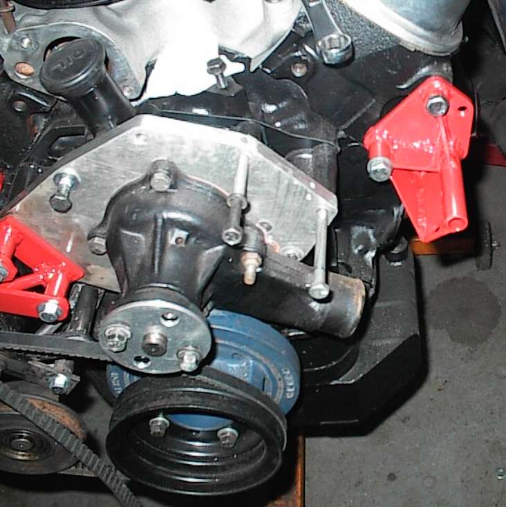
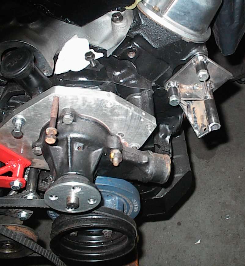 Next I welded up the back bracket for the alternator. I chose a large frame
95 amp Delco SI unit; they're cheap, reliable, and easy to work with. Thick
flat stock bolts to the head, with the alternator pivot bolt hole offset past
the outside of the head so the alternator pivots correctly to tighten the belt
when swung. The other tubes and bits are for triangulation. The long tube
butts up against the back of the alternator.
Next I welded up the back bracket for the alternator. I chose a large frame
95 amp Delco SI unit; they're cheap, reliable, and easy to work with. Thick
flat stock bolts to the head, with the alternator pivot bolt hole offset past
the outside of the head so the alternator pivots correctly to tighten the belt
when swung. The other tubes and bits are for triangulation. The long tube
butts up against the back of the alternator.
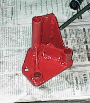 Finished bracket, radiused, deburred, primed, and painted.
Threaded hole on the side doesn't have any real purpose - there was metal
there, so I drilled and tapped it just in case I needed a place to mount a
torque strap or something.
 ...and mounted in place. The water pump inlet clears just fine. At the far
right corner of the T-sump is the screw-in plug Milodon wants you to use to
check the oil.
...and mounted in place. The water pump inlet clears just fine. At the far
right corner of the T-sump is the screw-in plug Milodon wants you to use to
check the oil.
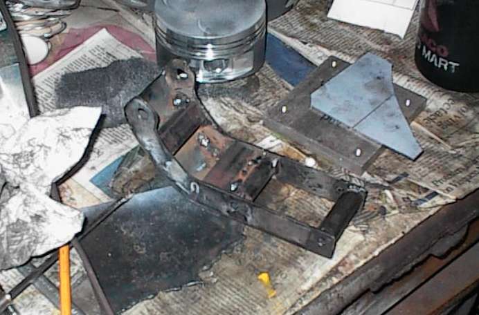
 Cardboard template for the front alternator bracket. It was very hard to
triangulate this part properly, so I went for thermonuclear overkill. This
bracket will form a cradle under the alternator, bolted to the water pump and
the cylinder head bracket I showed above.
Cardboard template for the front alternator bracket. It was very hard to
triangulate this part properly, so I went for thermonuclear overkill. This
bracket will form a cradle under the alternator, bolted to the water pump and
the cylinder head bracket I showed above.
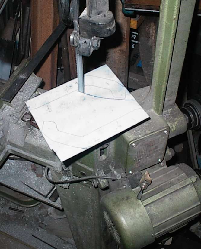 I cut a pair of these out of .090" steel sheet.
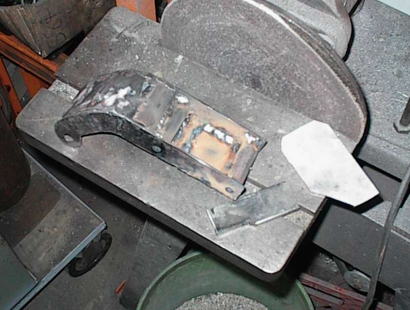
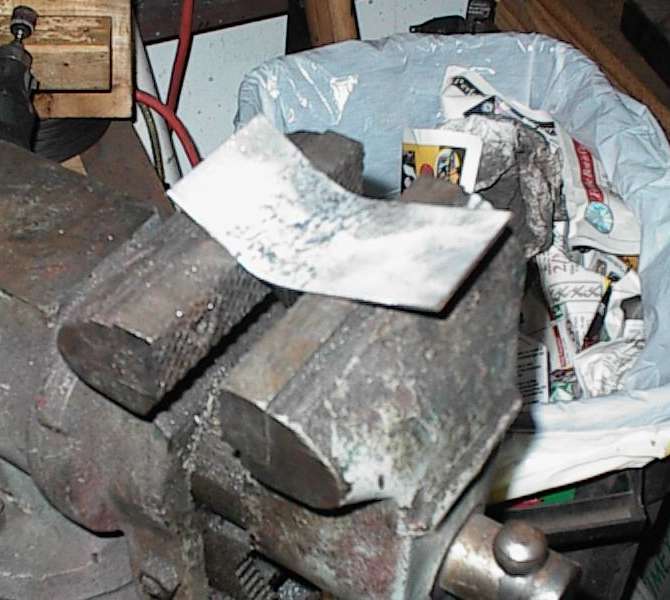 Next, I cut more .090, then hammerformed it into curves to match the side
plates. I had to make separate pieces for the top and bottom.
Next, I cut more .090, then hammerformed it into curves to match the side
plates. I had to make separate pieces for the top and bottom.
 Cradle with internal bracing welded in. I used square tubing instead of
"proper" triangulation. I figured there was enough metal there it wouldn't
really matter.
Cradle with internal bracing welded in. I used square tubing instead of
"proper" triangulation. I figured there was enough metal there it wouldn't
really matter.
 Another shot of the cradle.
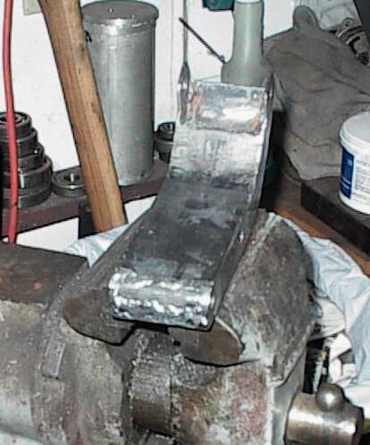 Finished cradle. The alternator pivots between the ears. Weld on the water
pump side is unsightly, but what the heck.
Finished cradle. The alternator pivots between the ears. Weld on the water
pump side is unsightly, but what the heck.
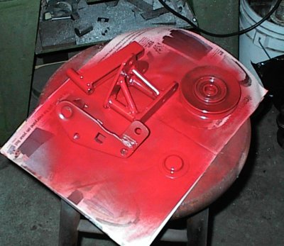 Painting all the fiddly bits. You can see the AC idler pulley and bracket
here.
Painting all the fiddly bits. You can see the AC idler pulley and bracket
here.
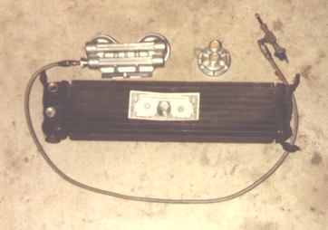 That's the original '79 RX-7 oil cooler. Huge, with internal regulator and
overpressure bypass. Compart its size to the dual filter block. Dollar bill
is for scale.
That's the original '79 RX-7 oil cooler. Huge, with internal regulator and
overpressure bypass. Compart its size to the dual filter block. Dollar bill
is for scale.