Joe Weinstein's 410 Windsor
This page: www.bacomatic.org/~dw/wein410/wein410.htm
Main page: http://www.bacomatic.org/~dw/index.htm
Last Updated: 16 Jul 2003
Author: Dave Williams; dlwilliams=aristotle=net
Joe Weinstein wanted something with more oomph for his '86 Saleen Mustang.
He also lives in San Francisco and didn't want any hassle with the California
smog check system. Specificially, he not only wanted it to pass smog, but for
every part the C.A.R.B. was concerned with to be 100% California legal.
The 1993 Cobra R came with a 351W, so as far as the CARB was concerned it was
a legal retrofit. As far as the CARB is concerned, the casting number on the
block *is* the engine; therefore, we needed a block with a correct casting
number. However, the F150 pickup roller block was *not* a legal interchange;
it had to be a *Mustang* block, which meant it had to be a Cobra R block...
and the Cobra R block had a unique Cobra R part number, and they're not
available as replacement parts from Ford! Joe got confirmation from Ford (on
dead trees, beloved of bureaucrats) that it was okay to use a truck block.
Paper is your friend...
The next problem was an intake manifold. There are lots of EO'd manifolds
out there, but the EOs are only valid for pickup trucks. (as of when we began
this project, back in '98) Apparently the CARB almost never checks to see
that an EO-marked part is actually valid for that particular vehicle, but we
were assuming a worst-case scenario. There were two legal 351W intakes - the
original Cobra R part, with either the original cast upper or the GT-40
tubular upper, and one from Saleen. There didn't look like there was a whole
lot of difference between them, so we went with the Ford bits for stealth
reasons. We knew that it was possible to flow more air through the cast upper
than the tubing upper if it was ported enough, so Joe sent the intake off to
Extrude Hone, who lightened his wallet substantially while taking probably 1/4
inch out of the runners. The intake is still going to be the cork in the
whole setup, but it's as good as it gets... that's indisputably 100% smog
legal for his particular setup, anyway.
I wavered back and forth on cam selection. The engine would have enough
cubes to tame a Ford E303, which is - somehow - smog legal, but reports from
people who have used them said passing smog could be iffy even with a 5.0. We
were building a much larger engine, but we still had to meet the same limits.
I decided to cheat and ordered a somewhat smaller Crane hydraulic roller that
was not EO'd. I already had an EO sticker from an E303... but when the new
cam came in, it came with the sticker! Crane had run it through the CARB
certification procedure between the time the catalog was printed and when I
ordered the cam.
The particular Edelbrock heads we used were the best available at the time.
We waited several months since various places kept talking about smogging a
better head, but we finally had to go with what was actually for sale.
There are some more pictures, but they're still on undeveloped 35mm waiting
for round tuits...
Internals:
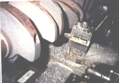
The crank is a 400 Ford casting, as usual. It has already been stroked to
4.06" and cut down to 240/Six rod journal size. The counterweights have been
profiled for piston clearance at TDC, which is why they have such an
exaggerated football shape. Now I'm cutting the OD down so it'll spin inside
the Windsor block.
I scrounged a matched set of 240/Six rods. They have to be narrowed on both
sides to fit the 400 crank. The rod bolt notches got polished, the bolts
replaced with ARP parts, the rods got resized, etc. The length is 6.2".
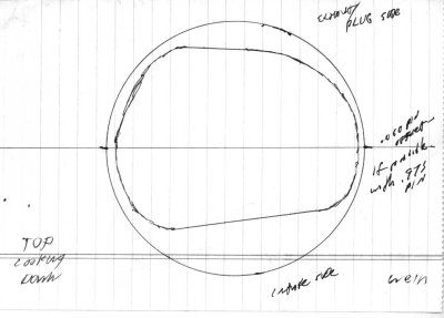
I made a tracing of the Edelbrock combustion chambers to FAX to Wiseco for the
pistons. You have to make it very plain whether you're showing the view from
the piston side or the head side!
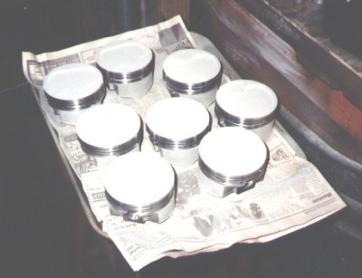
$750 worth of Wiseco custom forgings. They CNC-machined a mirror dish in the
tops according to a pattern they had that was pretty close to the one I sent.
They have .975" pins to match the 240 rods. Even with the dish tops the CR is
10:1. They've just been untaped after ceramic coating; the next step is to
moly coat the skirts.

The tag that came with the pistons gives their dimensions.
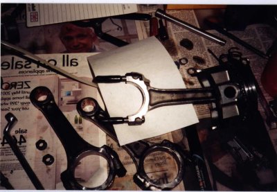
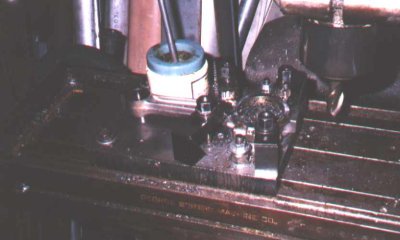
Even though this was only a 4.06" stroke the camshaft and connecting rods
collided. Only three, for some reason. Usually it's four. On the top of the
rod, hopefully made clearer by the white posterboard, is a lump of clay
showing the rod clearance to the cam. The rods that hit got their shoulders
beveled slightly. It didn't take much, just removal of the sharp corners.
Heads:
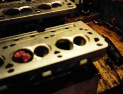
At the time we built the engine, the best of the California-smog-legal heads
were the Edelbrock Performers. This particular set came in with the seats
sunk far into the combustion chambers and stacks of shims under the springs,
which would have been an automatic return, except I had to work on them
anyway. I smoothed the seats in while polishing the combustion chambers,
blanded the bowl areas, and polished the exhaust ports and chambers.
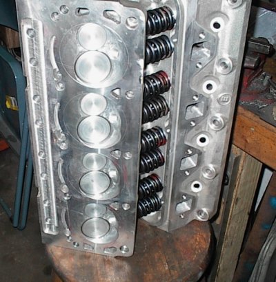
Here we are, complete. I never could get a bright finish on the chambers, but
they're smooth. The circular lines are plain old scribe marks to indicate the
limits of where I should grind on the chambers; they just *look* like O-ring
grooves. The valves have been extensively modified and ceramic coated. The
stock Edelbrock springs and retainers were replaced with Crane bits which were
needed for the high-lift-rate cam. This took considerable juggling with
offset keepers and shims to get the installed heights correct; the Crane kit
comes for Ford 5.0 heads which have different valve stem heights.
Assembly:
Just parts laying around; I probably put them there to get some room while
clearing some free space on the workbench.
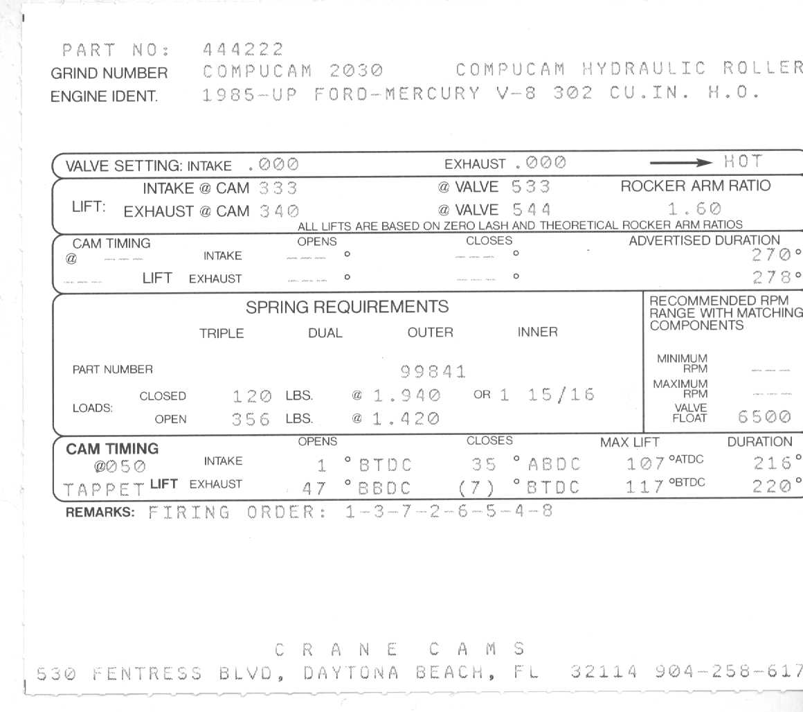
The card from the Crane cam gives its specifications. It's well within the
limit of being practical in a smog engine.
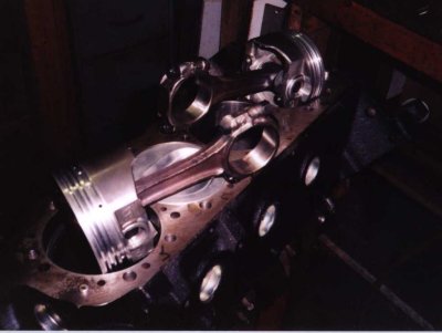
This is one of many trial fits; this time to get the pushrod length. I have
an adjustable pushrod and some -.030" solid roller lifters for doing this.
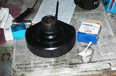
The 50oz 5.0 balancer needed a seal saver. This particular one even came with
a little tube of sealer. The seal savers are very thin and stretch quite a
bit on installation; sometimes getting one on without collapsing it can be a
trick.
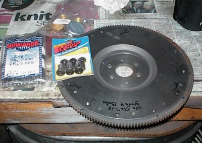
Brand new Ford 50oz 5.0 flywheel and matching ARP bolts.
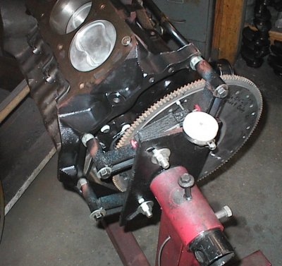
Final assembly now; here I'm checking flywheel runout. T.I.R. (total
indicated runout) was under .003"; dead nuts. You can see the "spectacle"
shape of the piston dishes pretty good in this shot.
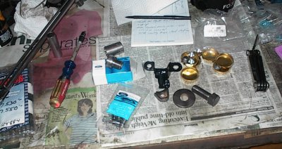
Just some assorted hardware - new timing cover dowels, new oil filter adapter
(the brand new Ford block didn't come with that, though it came with cam
bearings!), balancer bolt, and the weird triangular-looking thing is actually
the timing pointer. I had to do a slight hammer adjustment to make it line up
with the marks on the damper when I degreed the TDC mark in.
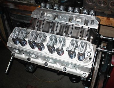
The cast rockers are just fine for the sub-6500 RPM range the engine will run
at. They're the pedestal mount type. Those are custom Howards Cams
pushrods. Cams vary in base circle, rockers vary in geometry, valve stem
length differences... it's amazing so many late model Ford guys don't run into
more trouble than they do. The customs give the roller lifters .030" of
preload as Ford recommends.
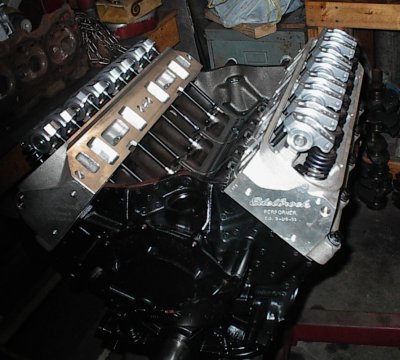
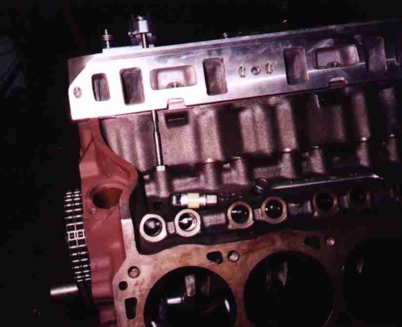
The assembled long block at last! The valve lift looks low, but that's an
illusion. The lifters are empty, so there's a lot of lost motion until you
prime the engine and get some oil to them. Ford recommends *not* pumping the
lifters full of oil since it makes it hard to check the preload on assembly.
Oil Pan:
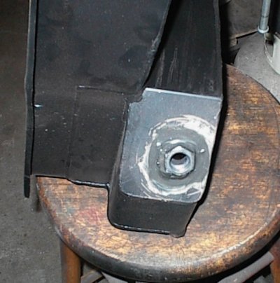
Joe's car has an oil sensor in the pan and the new Canton pan didn't come with
a bung for it. I MIG welded one in and smeared some epoxy around just in
case. The Canton came with a gold finish, but it was sort of mangy and all
the welding and hammering didn't help it any, so I painted it black to match
the rest of the engine.
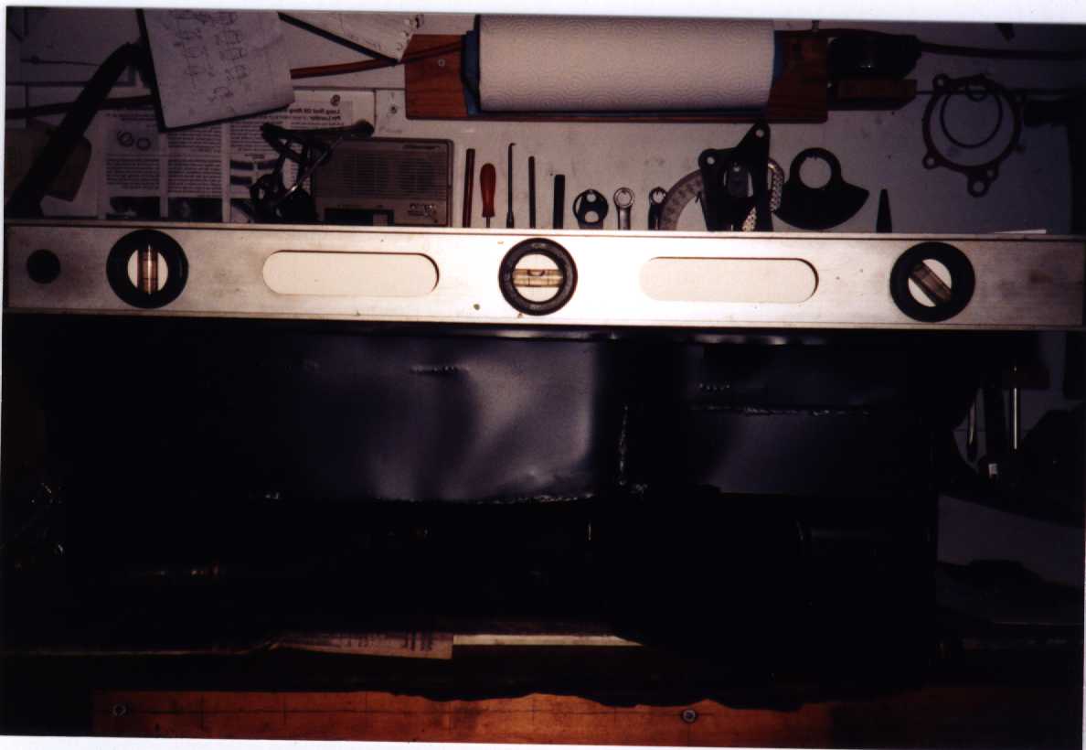
I tried to get a good shot of how wavy the Canton pan rail is. It's almost a
quarter inch out in various places. I didn't think to look before I started
modifying the pan; Canton's quality control used to be good. I've seen
a steady deterioration of their products over the last few years.
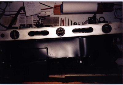
The bolts appeared to be able to pull it down snug, so I left it alone and
used it. At least, I tried. I was unhappy to find out the rail was not only
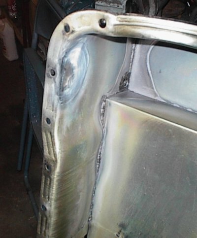
flat, but wouldn't clear the oil pump where it bolted up to the block!
The pan rail was wide enough to hit the oil pump where it bolted up to the
block. I looked at grinding on the pump for clearance, but it didn't look
like I could grind enough, and the Ford pumps are sort of weak looking down
there anyway.
The pan rails were already very wavy - Canton's quality control has gone to
crap - and I figured the pan would warp like an 8-track on a dashboard if I
just started torching on it. So I made a fixture of 1/4" steel flat to help
hold it straight.
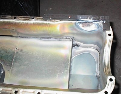
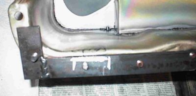
After the torch and hammer.
The resulting clearance dent worked fine, and the rail was unharmed. I could
have just beat and torched repeatedly, but I figured I'd get the opportunity
to use the fixture more than just this once...
Another view of the clearance dent.
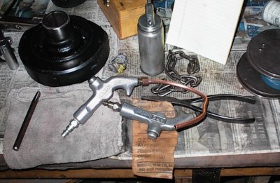
The Canton pan was full of MIG spatter from when it was made, and I kept
finding bits of metal in the myriad nooks and crannies where pieces of metal
overlapped. I used soap and water, the pressure washer, and lacquer thinner
sloshed inside to remove most of it, then modified a spare air gun with a 1/4
NPT compression fitting and some 1/4" copper tubing. That let me get into all
the places that would ordinarily have been inaccessible.
Canton provided a new Ford oil pump pickup tube with the pan. I liked it
better than Canton's homemade ones.
Intake:
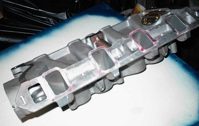
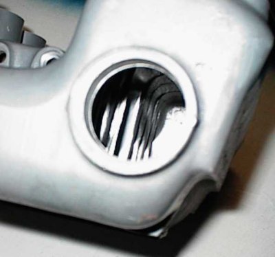
This is the fancy Extrude-Honed intake manifold...
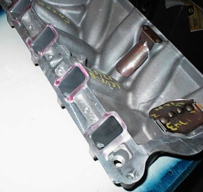
Manifold base. The ports are almost double the area of the ones on a stock
truck lower!
The Extrude Hone process isn't all that precise. Note how the openings aren't
quite rectangular and have wavy areas. It wasn't worth going after it with a
grinder. The process works rather well, considering the putty goes where it
wants to.
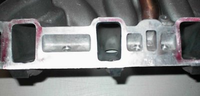
Better shot of the port irregularity.
Top side of intake. EH bolts steel "gasket" plates to this and the bottom
side to keep the glop from wearing big funnel shapes at the entrances and
exits.
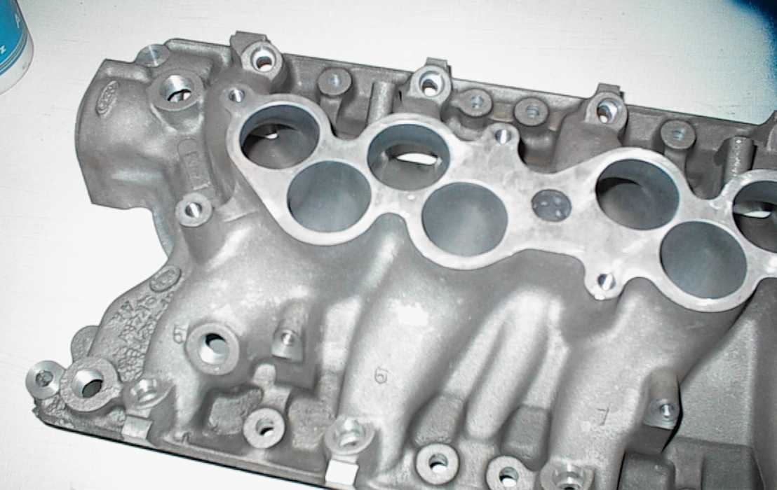
The runners on the Cobra intake are about as straight as you'll find for a
conventionally arranged Ford injection setup. See the kink in the runner to
the lower left? That's #5 cylinder, the one that causes a lot of problem with
Ford EFI intakes. The ports in the head sweep to the side; forward on that
side, backward on the passenger side. That's the wrong direction to line up
with the manifold runner, which is limited by the space needed for the
distributor. The Cobra intake puts the kink early and tries to straighten the
path out somewhat. Every little bit helps.
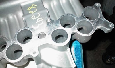
The upper isn't nearly as troublesome. The staggered rows, besides helping
line the ports up on the base, also allow larger diameter runners than if they
all had to be jammed side by side, like with the standard 5.8L truck intake.
The dividers at the plenum end got pretty thin, though the edges are nicely
rounded. Much better looking than the stock layout.
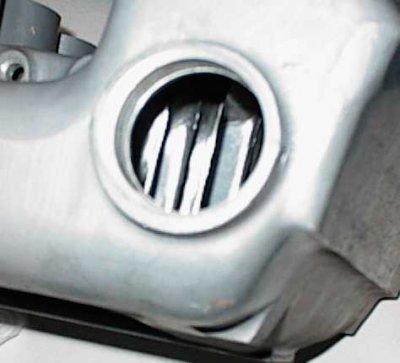
Another shot at a slightly different angle. I'd like to have one of those
fancy borescope attachments for the camera!
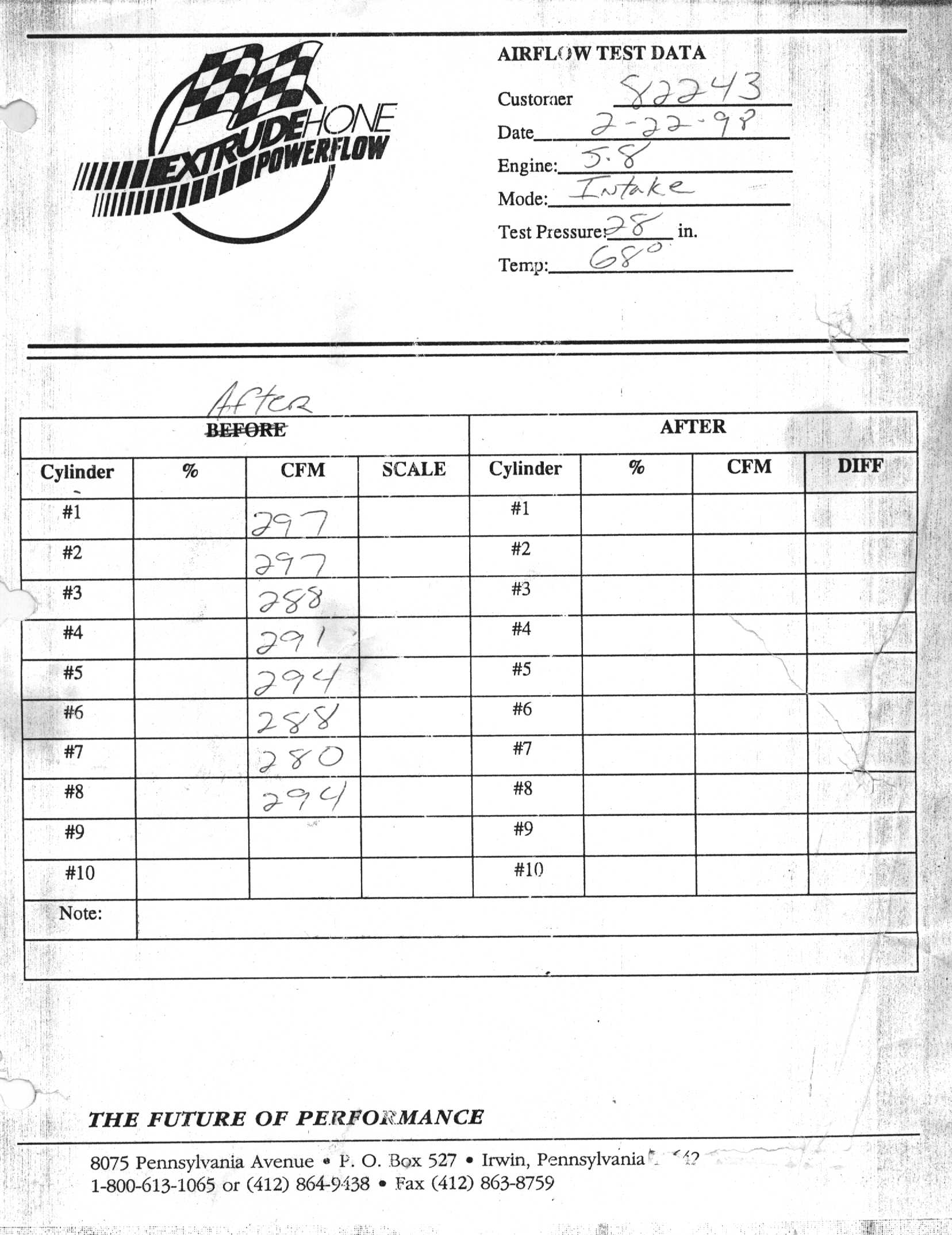
Extrude Hone provided a flow bench test sheet with the intake. ~290 CFM is
pretty good, but the long, long runners will make the intake resonant at a
lower RPM than I would have liked, but you can't have everything when you're
juggling E.O.'d smog bits around.
Fire-Up:
This is another one that had to be run before shipment. I had to build some
Ford brackets for the run stand, find a bellhousing to mount the starter to,
then a 5.0 starter, etc.
Here I'm assembling bits to fire it up before shipment. I didn't have any
reverse rotation water pump bits to match the timing cover, so I made up a
garden hose adapter. Ten feet of 5/8" clear plastic tubing comes off the
intake manifold, which is an old cast iron 2bbl part. I scrounged some
manifolds, adapted them to the 2" pipes on my run stand mufflers, found a 460
DuraSpark distributor and installed a Motorsport steel gear on it to match the
roller cam, stole the distributor cap, wires, starter, and valve covers off
TRX, etc... it takes more stuff than you'd think to fire one up.
After the engine was primed, the oil pressure gauge would hit 70 PSI before
the drill made one full revolution!
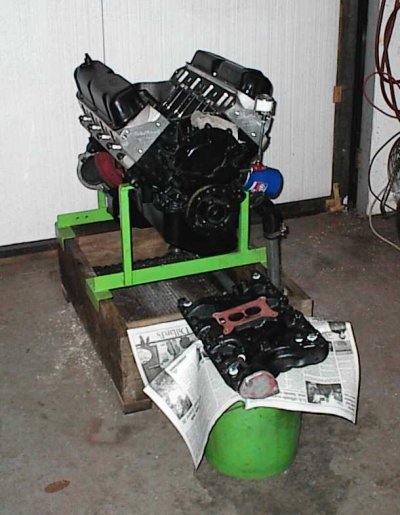
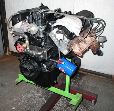
For some bizarre reason I didn't take a picture of the engine all dressed up
to run. Here it's mostly stripped back down. The thermostat housing blockoff
plate was originally made for another project that didn't go anywhere; I
reused it from the parts box.
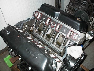
The white doohickies on the corners are Teflon sealer. That's a real 351W
intake, with 16 attachment bolt holes vs. the 12 used for the 302 or 351K,
which is what Ford called the Windsors after 1976, before they started calling
them Windsors again. [sigh] Anyway, the four extra bolts will leak water if
you use a 16-bolt intake with 12-bolt heads. I tapped the holes and screwed
in some short 1/2" bolts as plugs. Next time I need an intake to run an
engine like this I'll have it handy, but this sort of thing wound up taking a
lot of time.
Looks just fine inside... the oil was nice and clean when it drained out. Not
that I expected anything else, but paranoia is the engine builder's friend.
Shipping:
I've started taking lots of photos while crating engines now. Forklift blades
are a problem. An engine shipped to London had a fork run through the side of
the crate and through the oil pan; another sent to San Francisco was knocked
clean out the back side of the crate. Nothing will stop a forklift blade at a
running pace, but the freight companies always try to claim the engine was
improperly crated. Ford and Chevy just band an engine to a pallet and staple
some laths over it, not a proper crate at all. I do better than that...
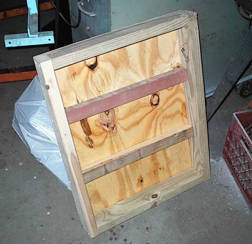
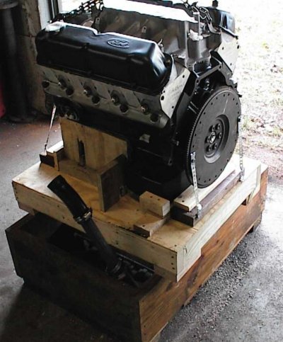
Crating one for shipment can be a hassle. Here's the beginnings of the base
platform; a 2x4 frame, 3/4" floor, and some odd-size pieces for cross braces.
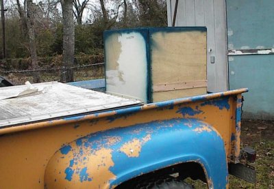
The box part is 1/4" plywood. It'll slide right over the top and get held
down with screws around the edges. The plywood was supposed to be some
cabinet doors, but it was about the right size, and I needed some plywood, and
besides, if I hadn't put the doors on after two years, I probably wasn't going
to... the the strips are where I spliced narrower pieces together. The
corners are 2x2s.
Everything taped off or plugged, lots of supports and blocks to keep it from
sliding around. The metal straps are just to keep it in contact with the
base; it can't slide around anywhere.
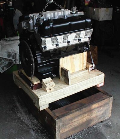
Lots of pieces of scrap lumber. The kickouts in the pan made it awkward to
use the usual pan rail method of supporting the engine. Most of the weight is
on the rails, with the sump in light contact with shims underneath. I didn't
want the whole weight of the engine sitting on the welds.
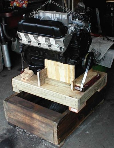
Yet another shot. Long wood screws keep everything together.
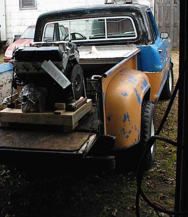
The upper intake would have made the engine too tall to lift high enough to
clear the tailgate, so it'll be added later. Temperature was about 18F and
windy right then... that's the chassis for a V8 Lotus 7 knockoff leaning
against the back of the house.
The water pump, fuel rails, an extra copy of the shipping instructions, and
other paraphernalia are fastened to the engine or crate with zip ties and/or
wood screws. Tyrannosaurus RX visible to the left, still waiting for the new
high-zoot driveline to replace the punked 302 and C4.
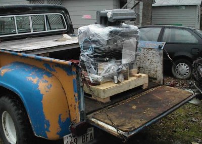
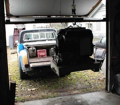
Several layers of plastic for waterproofing, in case the trucking company
leaves it outside in the rain. It's happened to me before. The upper intake
is just held on with a couple of bolts; it had to ride *somewhere*...
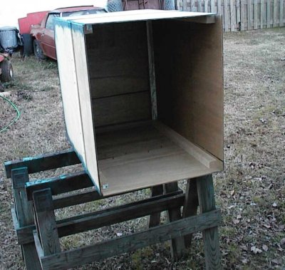
The plywood box slides down over the sides of the base and is held down with
screws. It made it to Griggs Racing in California without incident.
Specifications:
MAXIMUM OVERDRIVE RACING ENGINES
410W Ford stroker
completed 11/18/2001 for Joe Weinstein, Moraga, California
*****
351W Ford stroked to 4.06", stock 4.00" bore (408 CID)
Crane #2030 hydraulic roller cam, 216/222deg @ .050", .533/.544" lift
Edelbrock Performer aluminum heads
*****
warranty: If it breaks, you get to keep all the pieces you can find.
�
OIL FILTER-----------------------------------------------------------------
* oil filter application: 1978 Nissan 510, 2.0L 4 cyl (L20B)
Purolator Filter number L30119
Fram PH2850
Motorcraft FL-181
Wix 51452
These are full size, have no bypass spring, but do have the rubber
flapper for anti-drainback for faster oil pressure buildup on cold start.
This is technically a metric filter, but they will screw on just fine.
You might want to keep everything clean so you can take one back if they
have made a production change that keeps them from working.
*Check* for the rubber flapper and no spring, just in case the filter
maker has made a change. You can do without the flapper, but you don't
want the spring.
If you need a half height filter use the Purolator L22167 or equivalent.
�
TORQUE SPECIFICATIONS -----------------------------------------------------
--------torque---------------spec-----------thread---lube------------------
rod bolts
stretch to .0065 (ARP spec .0062-.0067) 3/8-24 ARP moly lube
main cap bolts
torqued to 95 ft-lb (Ford spec 90-100) 1/2-20 30wt ND oil
note: 1) use moly grease under bolt head
2) step 1: 50 ft-lb
step 2: 70 ft-lb (reverse pattern)
head bolts
torqued to 75 ft-lb (ARP spec 75) 1/2-13 ARP moly lube
note: 1) use hardened washers, ARP moly grease both sides of washer
2) block is blind tapped, no sealer needed
3) step 1: 50 ft-lb
step 2: 75 ft-lb (reverse pattern)
4) heads must be retorqued after two days, or after engine is first
run
damper (harmonic balancer) bolt
(Ford spec 70-90) 5/8-18 30wt ND oil
note: use automatic transmission fluid as lubricant when pressing damper on
intake manifold bolts
(Ford spec 23-25) 5/16-18 sealer
exhaust manifold bolts
(Ford spec 18-24) 5/16-18 antiseize
rocker bolts (torque 40 ft-lb) 5/16-18 30W ND oil
timing chain sprocket bolt
torqued to 40 ft-lb (Ford spec 40-45) 3/8-16 Loctite 272 blue
cam retainer plate
torqued to 10 ft-lb (Ford spec 9-12) 1/4-20 30wt ND oil
oil pan bolts
(Ford spec 7-9) 1/4-20 oil
(Ford spec 9-11) 5/16-18 oil
oil drain plug
(Ford spec 15-25) 1/2-20 oil
water pump bolts
(torque 12-18) 5/16-18 antiseize
timing cover bolts
(torque 12-18) 5/16-18 oil
1/4 NPT threaded oilway plugs Loctite Pipe Sealer With Teflon
or silicone sealer, Teflon pipe sealer
oil pump pickup
(Ford spec 9-11) 5/16-18 Loctite 242
oil pump cover plate
(Ford spec 9-11) 1/4-20 Loctite 242
oil pump body
(torque 30-35) 3/8-16 Loctite 242
spark plugs
14mm antiseize
bottom pulley to damper
(Ford spec 35-50) oil
valve cover
(Ford spec 3-5) 1/4-20 oil
fan to water pump
(Ford spec 12-18) 5/16-24 antiseize
flywheel bolts
(ARP spec 85) 7/16-20 30wt oil
�
COMPONENTS ---------------------------------------------------------------
Heads:
Edelbrock Performer aluminum heads
Edelbrock recommends Champion RC12YC for a baseline plug
1.94/1.60 valves
disassemble
polish exhaust ports
scribe chambers to cylinder bores
lay chamber walls back to block scribe lines
feather in valve seats in chamber
smooth valve seats in ports
polish combustion chambers and exhaust ports
install Crane 44308 springs and retainers, set spring heights
sandblast valve heads
coat valve heads with CBC2 ceramic thermal barrier, bake, polish
back and face cut valve for low lift air flow
regrind valve faces
regrind seats
clean
assemble
vacuum check
Valvetrain:
custom Howards 5/16" pushrods
7.53" installed on exhaust
7.55" installed on intake
lash caps on exhaust side
1.94" installed height on Crane #44208 valve springs, +.050 keepers
new Ford roller lifters
Competition Cams lifter spider
Competition cams aluminum pedestal roller rockers
Crane hydraulic roller cam #444222
216/220 deg duration at .050"; 270/278 advertised
.533/.544 lift with 1.6 rockers
valve float limit 6500 RPM with 356# springs
firing order: 1-3-7-2-6-5-4-8
Ford Motorsport M-6268-A302 roller timing set
Block:
new F4TE roller 351W block
clearance block for stroker crank
chase threaded holes
touch hone bores #600 finish with torque plates
install oil and water plugs
clean
paint semi-gloss black
Crank:
Ford 400
clean core
Magnaflux
offset grind to 4.060" stroke
turn mains .020" undersize
lay back snout ring for Windsor timing sprocket
shorten nose to Windsor length
turn down OD to fit Windsor block
shape OD to fit 6.2" rods
trim oil slinger flange down
cut second keyway for timing sprocket
install keys
bevel front edge to clear oil pump
polish journals
clean
balance to 50 oz 5.0 flywheel and damper
Rods:
Ford 300 Six, 6.2" long
hot tank
Magnaflux
glass bead
narrow sides on mill fixture
deburr and dress sides
knock out old bolts
cut shanks and caps
install new ARP bolts
resize big ends
chamfer big ends
balance
adjust side clearance on final assembly
bevel corners of #5, 6, 7 for cam clearance on final assembly
standard width rod bearings, not narrowed, std/.001, .001s on bottom
Pistons:
Wiseco custom forgings
4.00" diameter
custom CNC dished tops to mirror Edelbrock chambers
18cc dish volume
pin height: 1.26"
pin diameter: .975 (300 Six)
wristpin offset: .060"
ring widths: 1/16 1/16 .217 (3/16 + spacer)
mask, sandblast
demask, clean
coat TLML moly antifriction on skirts
coat CBC3 thermal barrier on tops
demask
bake
buff
wash
Speed-Pro file fit moly rings, 1/16 1/16 3/16
Assembly:
check rod to block clearances (.100 minimum)
check rod to cam clearances (.060 minimum)
check piston to crank clearances (.040 minimum)
degree cam
check rod side clearances
#1 .008
#2 .011
#3 .010
#4 .008
check crank end play
check valve/piston clearance
check pushrod length
hang pistons on rods (pressed pins)
file fit ring gaps
verify TDC on harmonic balancer
install new Ford roller pilot bearing
Induction:
Ford 1993 Mustang "Cobra R" 351W intake
Ford cast upper
Extrude Honed
flow figures (CFM@28"):
cylinder # CFM
1 297
2 297
3 288
4 291
5 294
6 288
7 280
8 294
fuel rails: Ground Pounder billet aluminum
Oiling:
Melling oil pump
new Melling 351W drive rod
Canton 351W-Fox rear sump pan
weld in bung for oil sensor
heat and bend rail for oil pump clearance (bad pan)
remove factory MIG spatters
straighten uneven rails as much as possible
tweak oil pickup to clear stroker crank
Miscellaneous:
turning torque, short block with cam, 35#
new Ford 5.0 flywheel, 50oz
flywheel .003 TIR
ARP flywheel bolts
Edelbrock aluminum 5.0 reverse rotation water pump
Ford 5.0 reverse rotation timing cover
ARP head bolts
Dana/Victor gaskets
Assembly:
find pushrod length
check valve/piston clearance
check rod/cam/block clearance
find TDC and adjust timing pointer
degree camshaft
file fit rings
check piston clearances
adjust rod side clearances
check lifter preload; adjust with lash caps
check flywheel runout
check oil pickup to pan clearance
trial assemble
final assemble
pre-oil with distributor tool
install carburetor intake, carb, distributor
run-in on run stand
remove carb bits, install EFI bits, crate
�
===========================================================================
assembly lubricants:
rod bearings: GM EOS
rings: Unilube two stroke oil
cylinder walls: Mobil 1 5w30
piston skirts: Mobil 1 5w30
wrist pins: GM EOS
head bolts - threads: ARP moly lube
main bolts - threads: 30wt ND
head, main bolts - under head: ARP moly grease
rod bolts: ARP moly lube
cam bolts: Loctite 272 blue
cam retainer plate bolts: Loctite 272 blue
cam lobes: 30wt oil
cam journals: 30wt oil
cam distributor drive gear: moly grease
cam retainer plate/sprocket: moly grease
crankshaft rear oil seal: GM EOS
�
===========================================================================
assembly notes:
Wrapper:
Leave the engine in its plastic wrap until you're ready to install it
Sealers:
sealers and thread goops usually work well when applied according to the
directions. The major part of the directions usually calls for the mating
surfaces or threads to be *clean*. Use acetone liberally to clean all metal
parts to be sealed.
don't get carried away with sealers. "Less is more". Excess sealer usually
winds up blocking the oil pump pickup. That is not good.
not all sealers are oil proof. Read the application charts before
purchasing. Use only O2-sensor-safe sealers
most sealers should be allowed to dry to some degree before the parts are
assembled. *Read the directions*. *Follow the directions*. Don't get
impatient. Have another beer, take a leak, or clean up some of your mess
while you wait.
Cleanliness:
keep your hands and tools clean and you have less chance of dropping crap
into your new motor and less chance of slicing a hand open when you slip
with a slimy tool. A 75 cent roll of paper towels and $1 tub of hand
cleaner will do.
Money:
Once you get everything ripped apart you will begin to hemorrhage from
the wallet as you find things that must or should be attended to while the
engine is out. Remember, everything always costs more and takes longer than
you figured.
�
INSTALLATION: ------------------------------------------------------------
Use sealer on the oil pressure sender.
Wire wheel or otherwise thoroughly clean the water temp sender. Install
with a minimal coat of antiseize. Sealer and corrosion can cause
resistance at the joint and will make the sender reading inaccurate.
Throttle linkage - oil it all while it's loose. If it's a cable, oil it
using a modeling clay funnel or motorcycle cable oiler
Make sure the battery cable isn't resting on a header or exhaust pipe.
Make sure the battery is grounded to both the chassis and the engine. It
probably has a big wire to the block or head and some little cheesy wire
from the intake manifold to the firewall. Use at least #4 (battery cable
size) direct from the negative post to the starter and to the chassis.
Your starter and headlights will appeciate it.
Your new motor will probably take *much* more oomph to turn it over than
the old one. You might want to have the starter looked at before you
put everything back together. It'll never be any easier to get to than
right now.
Use antiseize on the starter bolts.
Make sure the battery is fully charged before trying to start a new motor.
�
RUN-IN: -----------------------------------------------------------------
Make sure you don't have any loose wires or hoses in the way of the fan
before firing the engine. It is a great temptation to just start it up
with nonessentials hanging hither and yon.
Pour in 5 quarts of your favorite brand of non-synthetic oil, 10-30 or 10-40
weight, and screw on an oil filter. It probably wouldn't hurt to fill the
filter before putting it on.
With the "+"coil wire disconnected and spark plugs out, crank the engine over
until oil comes out the pushrods, or use an engine priming tool and a drill.
Attach the coil wire and valve covers, put the plugs in, attach plug wires.
Fill the radiator with straight water.
Smoke and noise will come from the motor as paint burns off, etc. Ignore
anything that doesn't sound terminal. Water temp will probably go right on
up there; it's okay as long as it doesn't go over 230 or boil over. If you
have near neighbors remember this will make a fair amount of noise.
Oil Viscosity:
Use the lowest viscosity oil required to maintain hot idle oil pressure of
at least 25 psi. This will circulate the maximum amount of oil through the
bearings. Very thick oil just goes right through the popoff valve built
into the oil pump and you can be starving the bearings while the guage
happily reads 60-80 PSI.