Author: Dave Williams; dlwilliams=aristotle=net
There are several X2 power drawbar designs out there. All the ones I found mounted the air cylinder on top of or in front of the mill head. I didn't care for the "in-your-face" position, so I decided to put mine on the side. The sidemount drawbar turned into a more complex design than an overhead, of course.
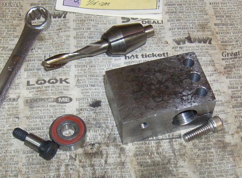 This is the rocker arm. It has to clamp to a 5/8" shaft and transfer over a
thousand pounds of load onto the drawbar. It's 1-1/2" wide with three
capscrews to get a good clamp on the bar.
This is the rocker arm. It has to clamp to a 5/8" shaft and transfer over a
thousand pounds of load onto the drawbar. It's 1-1/2" wide with three
capscrews to get a good clamp on the bar.
At this point, I've drilled 5/8" through, drilled and tapped for a 5/16"
shoulder bolt for the bearing to run on, and drilled and tapped for the clamp
screws. Now I have to mill a long slot to hold the bearing.
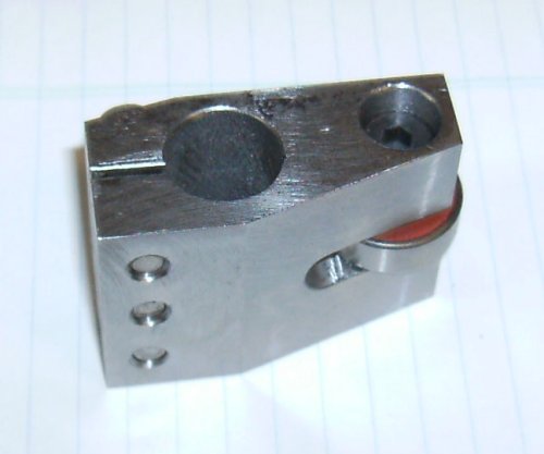 Bottom of the rocker; this is the part that contacts the drawbar. I used a
roller bearing since the rocker will make a slight arc across the end of the
drawbar as it pushes it down, and because the hard bearing won't wear.
Bottom of the rocker; this is the part that contacts the drawbar. I used a
roller bearing since the rocker will make a slight arc across the end of the
drawbar as it pushes it down, and because the hard bearing won't wear.
The shoulder bolt acts as the bearing's axle. Note the nice finish from the
flycutter I used to make the angle cuts.
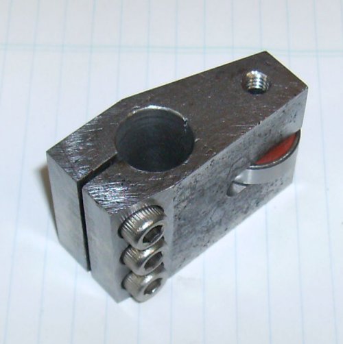 Cut across the top was decorative. What the heck, it's right on top, I'll be
looking at it often enough...
Cut across the top was decorative. What the heck, it's right on top, I'll be
looking at it often enough...
 To hold the axle we need some side supports. I cut them from some .090 CRS
scrap and tack welded them together.
To hold the axle we need some side supports. I cut them from some .090 CRS
scrap and tack welded them together.
 Drilling for the axle tubes, marked out for the mounting bolts.
 The axle tubes have been cut and faced on the lathe, the side plates have
been drilled and are temporarily bolted to the headstock.
The axle tubes have been cut and faced on the lathe, the side plates have
been drilled and are temporarily bolted to the headstock.
The side plates have been milled and belt sanded to shape, then separated.
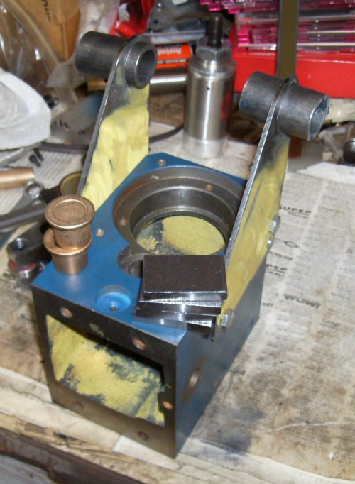
The four 1/4" blocks are spacers that go between the headstock and the side plates. The spacers were necessary to clear the Ron Steele belt drive kit. The belt would run fine on the large sheave, but there was no room to get the belt off without removing both side plates.
Two of the four bronze bushings the axle pivots in.
 Relationship of the parts, minus the side spacers.
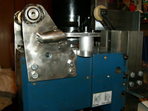
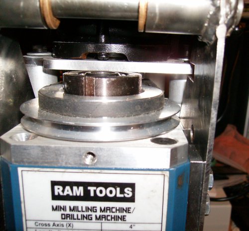 Side spacers in place, showing there's now just enough room to remove the
belt from the pulley, and the slot for the motor mount clearance.
Side spacers in place, showing there's now just enough room to remove the
belt from the pulley, and the slot for the motor mount clearance.
Things are still very tight here, but the belt can be moved from one sheave
to the other without use of tools.
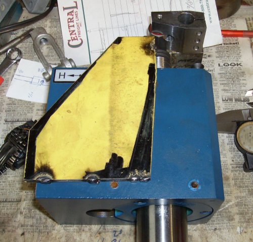
 The belt drive kit puts the drive motor on a pivot plate. When swung forward
to loosen the belt, the pivot plate hit the right side plate. I notched it
for clearance; this is the first crude bandsaw cutout.
The belt drive kit puts the drive motor on a pivot plate. When swung forward
to loosen the belt, the pivot plate hit the right side plate. I notched it
for clearance; this is the first crude bandsaw cutout.
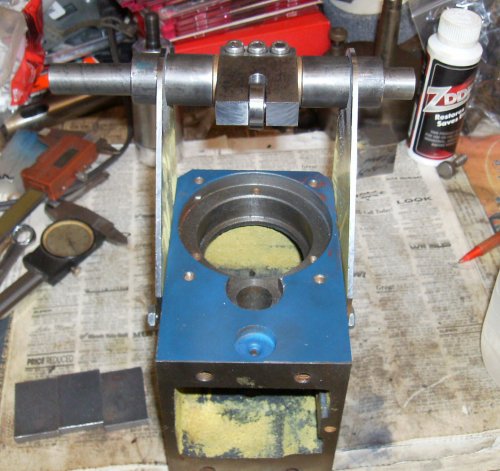
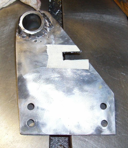
 The notch in the side of the support was unsightly, so I cut a piece of 3/4"
tubing off at an angle and welded it to the support to hide the notch.
The notch in the side of the support was unsightly, so I cut a piece of 3/4"
tubing off at an angle and welded it to the support to hide the notch.
Note the 3/8" hole below the cover; that's for the spindle lock rod.
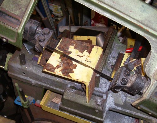
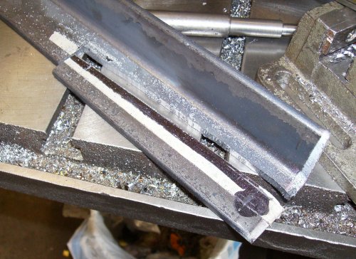 The air cylinder pushes on the actuating lever. I didn't have any 5/16" flat
stock on hand, so I sawed some out of a piece of angle iron.
The air cylinder pushes on the actuating lever. I didn't have any 5/16" flat
stock on hand, so I sawed some out of a piece of angle iron.
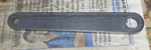 Finished operating lever. It's 5/8" on the big end, 7/16" on the small end.
 Sawing some 1/4" scrap to make the air cylinder bracket.
 Bracket has been flycut on the sides, now being drilled with the correct
tap drill size for 3/4-16 fine thread. The air cylinder will screw into the
front of the bracket.
Bracket has been flycut on the sides, now being drilled with the correct
tap drill size for 3/4-16 fine thread. The air cylinder will screw into the
front of the bracket.
 Skipping a few operations, this is the mounting block A 1/2" shoulder bolt
sticks out one side (where the magnet is now) to make a pivot for the air
cylinder. The two top bolts just clear the shoulder bolt, the left hand holt
is just past the end of the bolt. Sometimes ya gotta put the mounting bolts
where there's nothing else in the way...
Skipping a few operations, this is the mounting block A 1/2" shoulder bolt
sticks out one side (where the magnet is now) to make a pivot for the air
cylinder. The two top bolts just clear the shoulder bolt, the left hand holt
is just past the end of the bolt. Sometimes ya gotta put the mounting bolts
where there's nothing else in the way...
 I used 1/4-20 for the mounting bolts, same as everyplace else. If they don't
hold, I'll step up to 5/16" hardware.
I used 1/4-20 for the mounting bolts, same as everyplace else. If they don't
hold, I'll step up to 5/16" hardware.
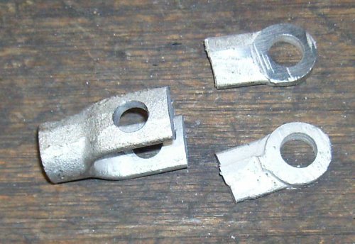 The air cylinder is designed for a 7/16" clevis. The one I bought with the
cylinder was far too long, so I drilled a new hole and cut off the excess.
The air cylinder is designed for a 7/16" clevis. The one I bought with the
cylinder was far too long, so I drilled a new hole and cut off the excess.
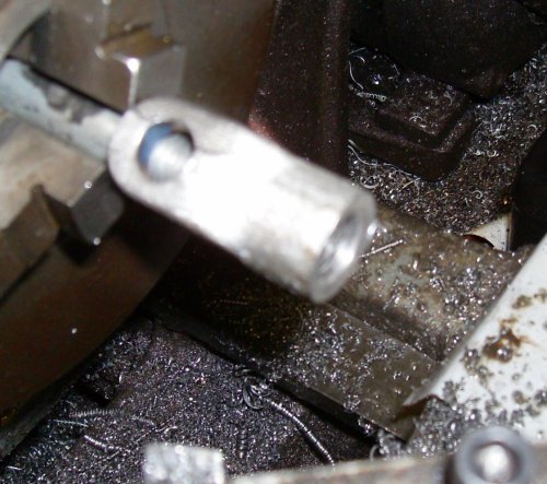
 A long bolt provided a handle for rounding off the cut end.
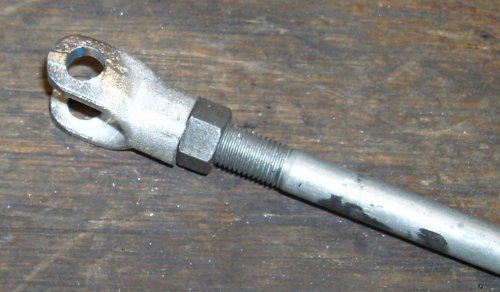
 The part the jam nut goes against was rough, and not square anyway. I faced
it off on the lathe.
The part the jam nut goes against was rough, and not square anyway. I faced
it off on the lathe.