Seig X2 minimill CNC conversion, Part 1: X/Y ballscrews
brought to you by: Dave Williams
This page: www.bacomatic.org/~dw/tool/x2/xy/xy.htm
Main page:
http://www.bacomatic.org/~dw/index.htm
Last Updated: 18 Sep 2008
Author: Dave Williams; dlwilliams=aristotle=net
Though CNCFusion's web site talks about installing the kit on an assembled
mill, it's much easier to take it apart. In fact, you'll probably wind up
taking it all apart several times. Fortunately it's easy to disassemble.
Mine was also full of grit and cast-iron swarf, which was even on the gears
inside the head.
quandrant2005's videos on YouTube look as if all he had to do was tilt his
machine back and install the CNCFusion kit. Mine wasn't nearly as simple.
There appears to be considerable variation in the castings, and I'm happy
that CNCfusion decided to go for maximum travel with a little fiddling if
needed, but it was still a surprise when nothing seemed to fit.
This is more or less what I did for my installation:
1. remove electricals
(get stuff out of the way)
four socket head screws hold motor mount plate to main head casting
four Phillips screws hold the control box lid; four more hold the
box to the casting
four Phillips screws hold the motor driver lid; three hold the box to
the column
two Phillips head screws hold grounding wires from the driver box to
the column
set all the bits off to the side
2. remove column
(you need to get under the base, etc.; it's easier to do if it's apart, you
have to disassemble the table anyway, and it's easier to clean it this way)
it will help if the base is still bolted to the shipping platform
run the head about halfway down the column
loosen the big nut that holds the column to the base. Keep one hand
on the column so it doesn't fall over. Remove the nut and
thick washer.
slide the column away from the base, off the long stud. It is heavy
and awkward to hold on to, and covered in grease. If the
base isn't anchored to something it may want to slide around
lay the column on its back, taking care not to bend the feed levers
3. disassemble base
remove X handwheel; it is double-nutted
loosen gib screws one turn
remove the left end cap from the table
loosen the set screws that hold the X-axis bracket
loosen the set screw that holds the leadscrew nut to the saddle
slide the table off to the right
the gib will fall out. Note: my gibs had nasty burrs where the screws
rode. Though the gibs are some kind of steel, they're dead
soft, so a file or sandpaper will work fine. If you use
power tools, be cautious.
run the saddle to the back
remove the two screws from the front of the base, that hold the
Y-axis bracket
loosen the single Allen screw that holds the Y-axis nut to the saddle
slide the leadscrew out
4: clean
I used car engine degreaser and the garden hose, then blew the pieces
with compressed air. A light spray of WD-40 to delay rust.
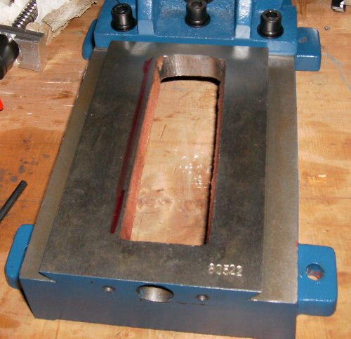
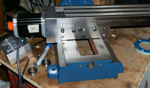
5: clearance base casting for Y-axis leadscrew
get the Y-axis (short) leadscrew assembly out of its wrapper
remove the Lovejoy coupler
remove the spanner nut. Mine came from CNCFusion run down just snug;
I was able to get it off with my fingers
slide the motor mount off. The ball bearings are loose and will fall
out if you're not careful. Do not remove the ballnut.
slide the Y-axis leadscrew in from the bottom. The threaded end
sticks through the front of the base casting.
put the back bearing in the motor mount and attach it to the base with
the screws provided. Snug the screws down; don't over tighten.
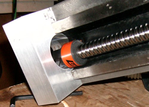
the ballscrew is made as long as possible for maximum Y travel, but
there are variations in the coring of the base casting. With
some castings, the screw will bottom out before the motor
mount is tight. My arbitrary decision was that .005" to .050"
would be enough clearance. I wound up with .100" due to
enthusiastic grinding.
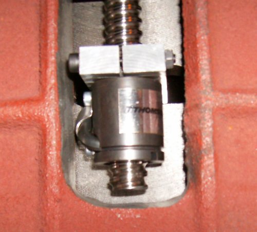
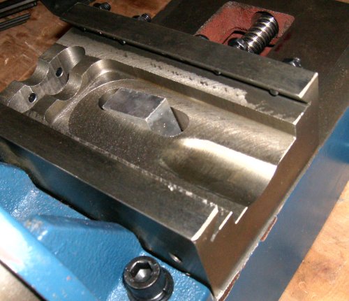
 the left side of the ball nut has the recirculating tube for the
balls. On my mill, the ball nut scraped the rough side of
the clearance slot, so I had to grind some there, too.
the left side of the ball nut has the recirculating tube for the
balls. On my mill, the ball nut scraped the rough side of
the clearance slot, so I had to grind some there, too.
if you don't have enough clearance, file or grind the casting. Then
you get to clean and oil it again.
if you have access to another mill you could save a lot of grinding
 don't get too crazy clearancing the back of the base casting. More
then 1/8" or so clearance and the ballscrew may be able to
run off the last thread and drop balls out. If you want to
be precise, check your screw and nut and see exactly how far
the nut may go before you can lose your balls. Someday you
might need that extra .100" or so of Y travel
don't get too crazy clearancing the back of the base casting. More
then 1/8" or so clearance and the ballscrew may be able to
run off the last thread and drop balls out. If you want to
be precise, check your screw and nut and see exactly how far
the nut may go before you can lose your balls. Someday you
might need that extra .100" or so of Y travel
6. Y-axis leadscrew nut
make sure the threads on the end of the screw are clean, and the
threads in the special spanner nut are clean.
put a drop of oil on the threads
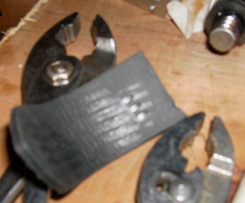 CNCfusion's forum says you should be able to hold the ballscrew firmly
in one hand and use pliers to run the nut down snugly against
the ball bearing. This wasn't even in the same universe as
the screw and nut I got. Using a piece of old leather belt
to pad the jaws, I tried holding the screw with 10" pliers
and still couldn't get enough of a grip to run the threads
past the locking ring in the nut. I was leery of using Vise
Grips, so I picked away at the plastic locking ring with a
penknife until I could run the nut on. I figured I could use
a drop of Loctite later if needed. You might try padding the
screw with leather or wood and holding it in a bench vise to
run the nut on and off a few times to loosen it up. My nut
has plier marks all over it now. Surely there's a spanner
wrench to fit the thing, somewhere...
CNCfusion's forum says you should be able to hold the ballscrew firmly
in one hand and use pliers to run the nut down snugly against
the ball bearing. This wasn't even in the same universe as
the screw and nut I got. Using a piece of old leather belt
to pad the jaws, I tried holding the screw with 10" pliers
and still couldn't get enough of a grip to run the threads
past the locking ring in the nut. I was leery of using Vise
Grips, so I picked away at the plastic locking ring with a
penknife until I could run the nut on. I figured I could use
a drop of Loctite later if needed. You might try padding the
screw with leather or wood and holding it in a bench vise to
run the nut on and off a few times to loosen it up. My nut
has plier marks all over it now. Surely there's a spanner
wrench to fit the thing, somewhere...
7. install Y-axis leadscrew
hold the short gib into the saddle casting and slide it onto the base.
the gib screws go to the front on top and the right on bottom.
slide the saddle all the way to the back of the base
install the screw and motor mount. You may have to fiddle a bit to
get the lug on the ballnut into the hole in the saddle.
snug the motor mount screws to the base
slide the outer ball bearing into outside of the motor mount
install the spanner nut. Those look like ordinary ball bearings, so
they're not intended to take a whole bunch of side load.
That's a 32-pitch thread, so "just snug" should do. If it
loosens up under load you can always snug it tighter; if you
ding a bearing race it will have to be replaced.
CNCfusion's web site says to run the saddle all the way forward and
tighten the ballnut retaining screw. "All the way forward"
means "as far as you can go and still get the Allen wrench
between the saddle and the motor bracket." The purpose of
running the saddle forward is to try to align the bearings
and the ballnut. Run the saddle forward, loosen and re-snug
the motor bracket screws, then loosen the ballnut bracket
screw in the saddle and snug that. Now push the saddle all
the way forward and back. If it gets stiffer at one end,
you'll have to twiddle the ballnut bracket position until
the saddle moves freely throughout its travel.
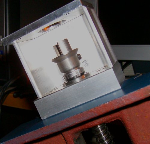
assemble the Lovejoy bits onto the ballnut and slide the motor shaft
through the bracket into the Lovejoy coupler. Snug set
screws, making sure the motor side screw is on the flat in the
shaft.
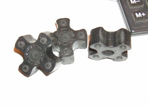 there was .060 or so negative axial clearance in my Lovejoy couplers.
That is, the motors would fail to touch the brackets by that
amount, and tightening the mounting screws put a lot of load
across the stiff plastic coupler crosses. I didn't like the
idea of that much end load on the motors. I emailed
CNCfusion and they said it wouldn't hurt anything. I still
didn't like that much preload, so I used a 1/4" Forstner bit
to put some simples in the crosses. Everything slid together
nicely then
there was .060 or so negative axial clearance in my Lovejoy couplers.
That is, the motors would fail to touch the brackets by that
amount, and tightening the mounting screws put a lot of load
across the stiff plastic coupler crosses. I didn't like the
idea of that much end load on the motors. I emailed
CNCfusion and they said it wouldn't hurt anything. I still
didn't like that much preload, so I used a 1/4" Forstner bit
to put some simples in the crosses. Everything slid together
nicely then
a ball-end metric Allen wrench would be a big help when installing
the motors, or soldering or brazing the provided wrench to a
piece of tubing so you can turn the wrench 360 degrees instead
of 90 degrees at a time. I found a long ball-end wrench set
at the local hardware store for $10. It was worth at least
that much not to have so much hassle with the screws. You
will probably run those screws in and out *many* times while
fitting the parts to the mill.
it's easier to see what you're doing if you turn the mill base
upside down
when wrestling the mill around the bench, try not to grab the Y-axis
motor mount no matter how convenient it looks as a handle
8. X-axis leadscrew
 drop the X-axis leadscrew into the saddle. The threaded end goes to
the right.
drop the X-axis leadscrew into the saddle. The threaded end goes to
the right.
set the gib in the front of the dovetail. Make sure the dimples line
up with the gib screws
slide the table on from the left to right
 see if the ballnut contacts the underside of the table at any point.
if so, the table will have to be clearanced. Mine would
grate over rough bits and then jam about 2/3 of the way
across, even without the screw being mounted in its end blocks.
see if the ballnut contacts the underside of the table at any point.
if so, the table will have to be clearanced. Mine would
grate over rough bits and then jam about 2/3 of the way
across, even without the screw being mounted in its end blocks.
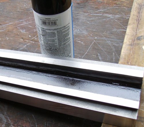 the back and top of the ballnut contacted the table, but the most
interference was the ball return tube on the front of the nut.
I removed +1/8" of the casting to get room for the nut.
the back and top of the ballnut contacted the table, but the most
interference was the ball return tube on the front of the nut.
I removed +1/8" of the casting to get room for the nut.
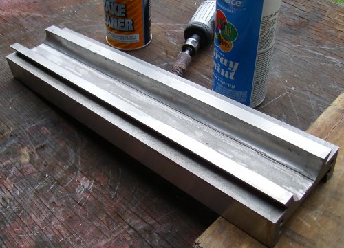
It took half a dozen tries to get things to move freely. I was concerned
about warping the table if I removed too much metal. Black spray paint
was a convenient way to see where the nut was hitting. Since the ballnut
is offset, the entire width of the table doesn't need to be ground to
clear it.
I had to take some off the middle to clear the ballscrew as well.
the C-shaped bit with X-/X+ goes on the right side, spacing the
original thrust washer and bracket out
the rectangular motor mount block goes on the left
 screw the Lovejoy coupler to the X motor, assemble the cross and
inner joint, and feed them through the hole in the motor
mount. The motor-side coupler must be tightened before
mounting the motor unless you drill a hole in the mounting
bracket to allow access.
screw the Lovejoy coupler to the X motor, assemble the cross and
inner joint, and feed them through the hole in the motor
mount. The motor-side coupler must be tightened before
mounting the motor unless you drill a hole in the mounting
bracket to allow access.
tighten screws, making sure motor shaft flat is under the screw.
The ballscrew doesn't have a flat. I recommend filing or
milling a flat - that part of my screw was fairly soft, and
the setscrew raised a large burr where it contacted the
shaft. This made removing the coupler very difficult; I
had to pad everything, put it in the big vise, and beat it
out with a brass drift since I didn't have a puller small
enough to do the job. I probably tightened the set screw
too much, but a flat would still keep you from marring the
shaft.
if you try to tighten the motor with negative clearance in the Lovejoy
coupler, it can jam the ballscrew part of the coupler onto
the screw too tightly to be removed easily. Remember, you
can't just beat it off without damaging the ballnut.
 there is very little clearance between the thrust bearing spacer
(the spacer on the right side of the table) and the ballnut.
On my particular machine, lifting the spacer up with my finger
while tightening the through-bolts was enough to get by
there is very little clearance between the thrust bearing spacer
(the spacer on the right side of the table) and the ballnut.
On my particular machine, lifting the spacer up with my finger
while tightening the through-bolts was enough to get by
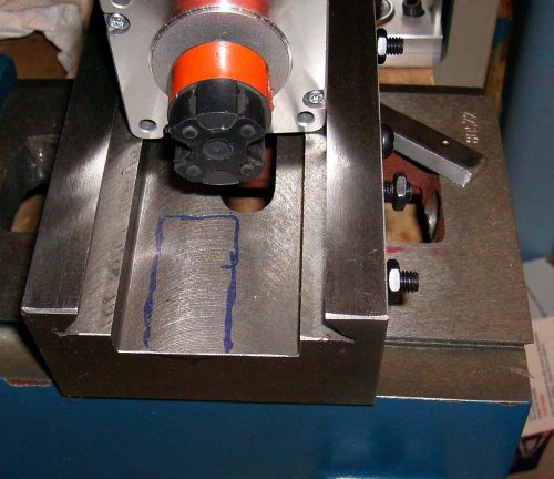
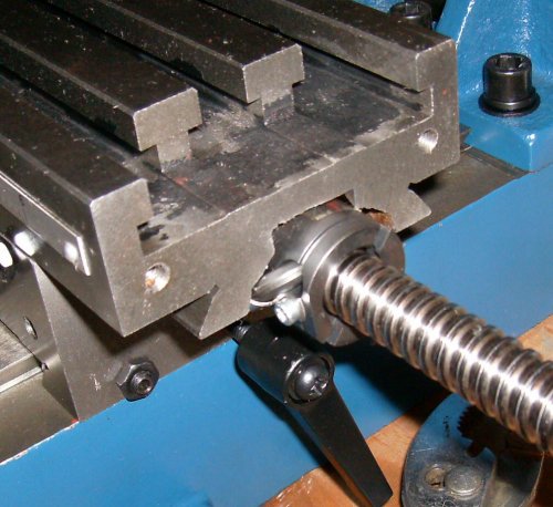
 unfortunately, on the left side of the table the Lovejoy coupler kit
the saddle casting before the table moved all the way to the
right. The saddle has to be relieved to accomodate the
length of the coupler. I ran the table to the right until
the coupler touched the saddle, ran a felt tip pen around
the coupler where it touched the table, and disassembled the
mill yet again.
unfortunately, on the left side of the table the Lovejoy coupler kit
the saddle casting before the table moved all the way to the
right. The saddle has to be relieved to accomodate the
length of the coupler. I ran the table to the right until
the coupler touched the saddle, ran a felt tip pen around
the coupler where it touched the table, and disassembled the
mill yet again.
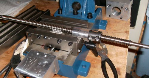
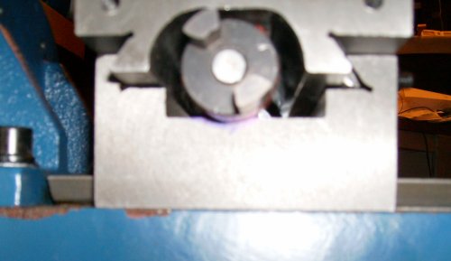
 Here we go! The table runs all the way to X+ now.
 I used a carbide burr and abrasive rolls in a 1/4" die grinder and
took +1/4" out.
I used a carbide burr and abrasive rolls in a 1/4" die grinder and
took +1/4" out.
 Later, I saw some pictures of another
CNCFusion conversion on the web, and it had a smaller diameter
yoke on the X screw - the same one that was on my Y screw.
If I had looked closely, I could have swapped the yokes and
everything would have cleared. However, I now have room for
helical flex couplers if I want to upgrade.
Later, I saw some pictures of another
CNCFusion conversion on the web, and it had a smaller diameter
yoke on the X screw - the same one that was on my Y screw.
If I had looked closely, I could have swapped the yokes and
everything would have cleared. However, I now have room for
helical flex couplers if I want to upgrade.
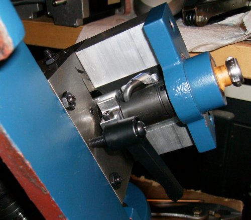
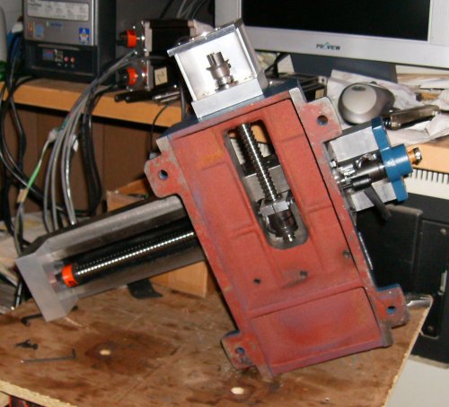 Finished installation from underneath.
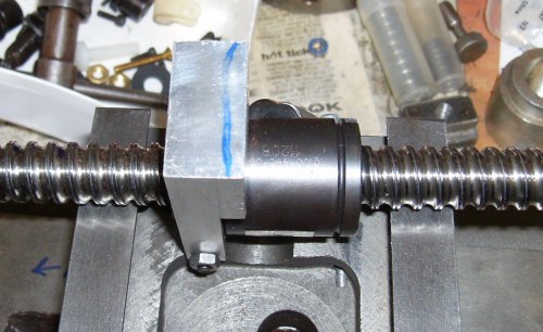 The X travel still seemed a bit rough in places. When I disassembled the
machine to do the limit switches, I noticed some screw marks in the Y ballnut
bracket. It was rubbing the X ballscrew.
The X travel still seemed a bit rough in places. When I disassembled the
machine to do the limit switches, I noticed some screw marks in the Y ballnut
bracket. It was rubbing the X ballscrew.
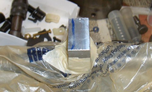 Some tape, some plastic bags, and a trip to the disc sander, and that problem
is fixed easily enough...
Some tape, some plastic bags, and a trip to the disc sander, and that problem
is fixed easily enough...
The CNCFusion Z-axis parts bolted right on without a hitch.
Unfortunately, the ballnut and screw blocked access to the gib screws
on the head casting. After looking at things for a while I decided
not to use the CNCFusion bits as delivered.